Rollout interface linkage for network protectors

a network protector and interface technology, applied in the field of network protectors, can solve the problems of circuit breakers tripping, requiring modification of the housing assembly, and increasing the size of the vault to accommodate larger network protectors

Inactive Publication Date: 2006-02-14
EATON CORP
View PDF9 Cites 7 Cited by
  • Summary
  • Abstract
  • Description
  • Claims
  • Application Information

AI Technical Summary

Benefits of technology

[0022]To close the circuit breaker the user moves the external handle to a closed position. The closed position requires the housing shaft to rotate from the neutral position in a direction opposite the direction of the open position. Thus, the rollout shaft tooth is moved away from the hub tooth and does not act upon the hub tooth. Thus, the hub assembly collar and hub arm remain in the second position while the rollout shaft continues to rotate into the closed position. The rollout shaft is required to move through a greater arc to effect actuation of the electrical close assembly. Once the rollout shaft

Problems solved by technology

Given their urban, subterranean location, increasing the size of the vault to accommodate larger network protectors is costly and difficult.
Thus, before the housing assembly is opened, the circuit breaker was tripped.
That is, the shaft typically cannot move through a greater arc, e.g. greater than ninety degrees, as that amount of rotation may cause the coupling device to wrap around the sh

Method used


Image

  • Rollout interface linkage for network protectors
  • Rollout interface linkage for network protectors
  • Rollout interface linkage for network protectors

Examples


Embodiment Construction

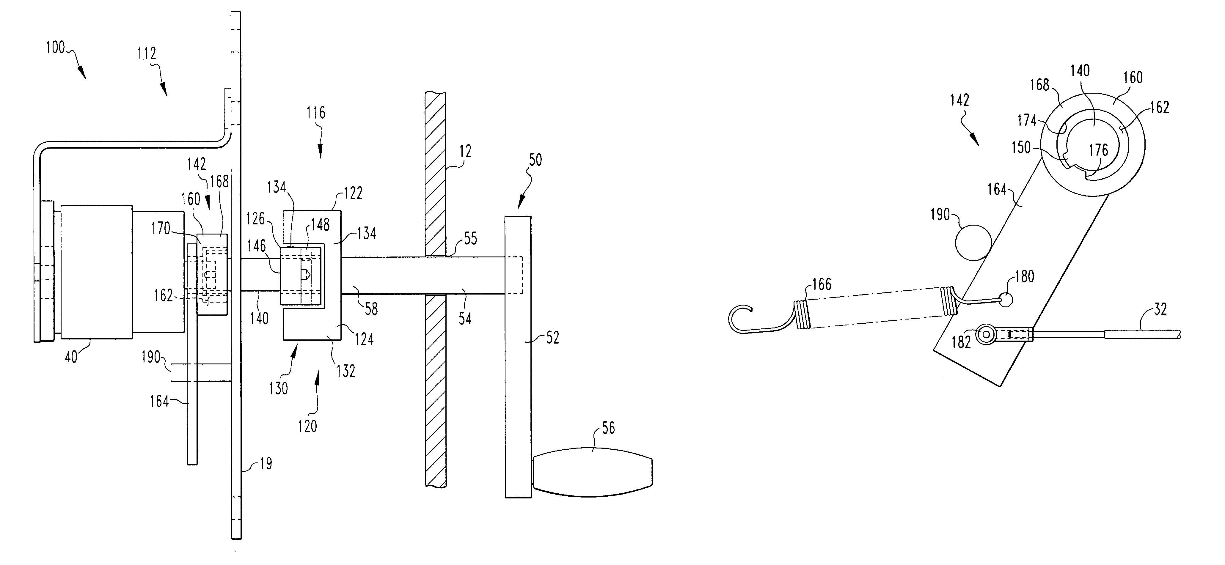
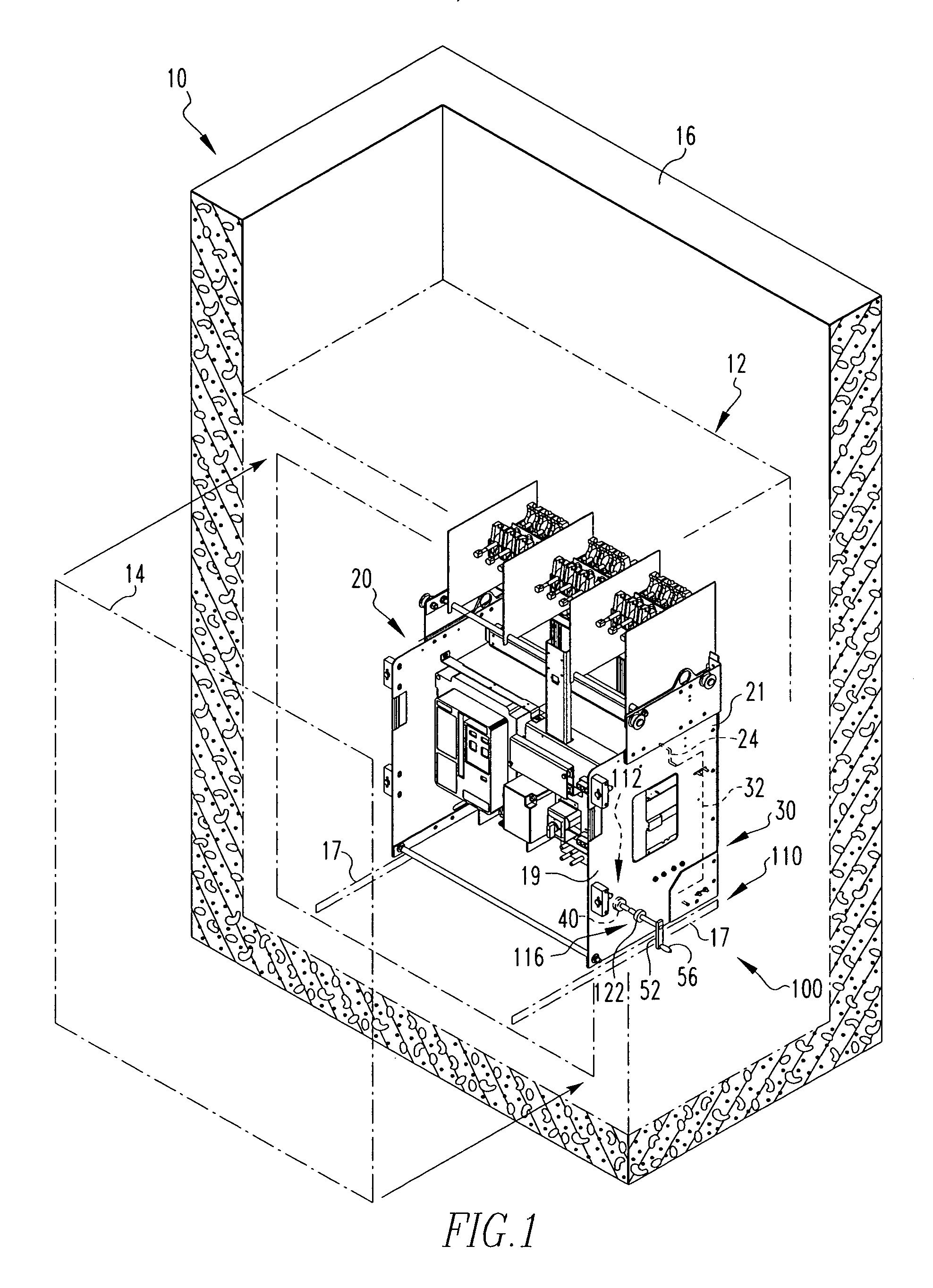
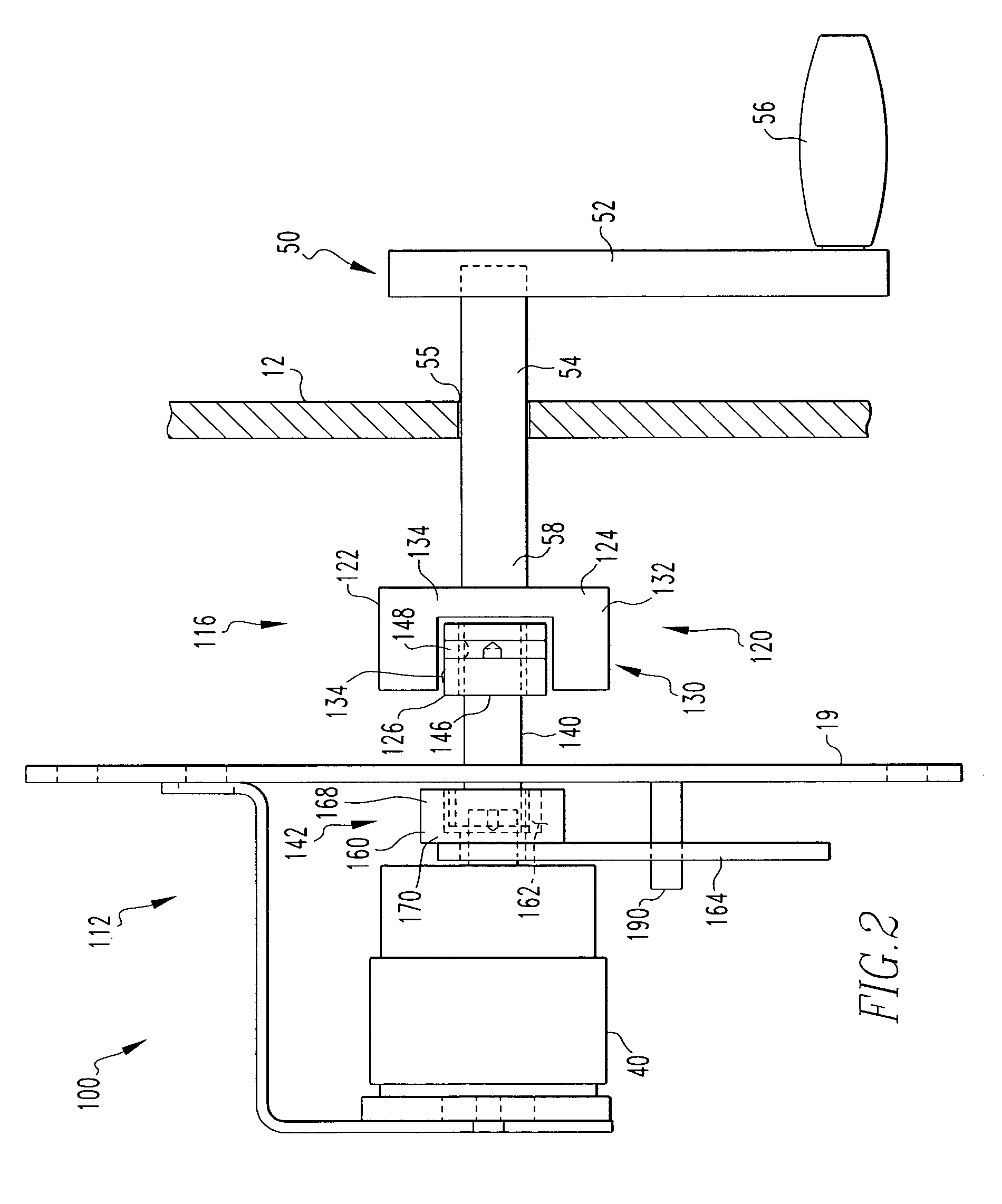
[0033]As shown in FIG. 1, a network protector 10 includes a housing assembly 12 which includes a movable door 14 that is attached to the housing assembly 12. The housing assembly 12 has an external operating handle assembly 50 (described below) which passes therethrough. The operating handle assembly 50, as will be described below, interacts with the trip bar 24 and may be actuated while the door 14 is closed. The housing assembly 12 is structured to be placed within a vault 16. The vault 16 is typically made of concrete or a similar material. The two primary network protector components, a circuit breaker 20 and a relay 22 are disposed within the housing assembly 12. The circuit breaker 20 is supported by a rollout carriage 19. The housing assembly 12 includes a set of rails 17 (shown schematically) upon which the rollout carriage 19 rests so that the circuit breaker 20 may be moved into and out of the housing assembly 12. The rollout carriage 19 includes at least one sidewall 21 d...


PUM


Abstract

An interface linkage assembly for a network protector is provided. The network protector includes a circuit breaker structured to move in and out of a housing assembly, and having a mechanical trip assembly and an electrical close assembly. The interface linkage includes a coupling device, a housing assembly portion and a rollout portion. The coupling device has a first component and a second component. The housing assembly portion is coupled to the coupling device first component. The rollout portion is coupled to the coupling device second component. The rollout portion is structured to be coupled to the mechanical trip assembly and the electrical close assembly, and further structured to move the mechanical trip assembly over a lesser arc and the electrical close assembly over a greater arc.

Description

BACKGROUND OF THE INVENTION[0001]1. Field of the Invention[0002]This invention relates to a network protector having a cable trip assembly and an electrical close assembly, more specifically, to a network protector which incorporates an interface linkage assembly structured to operate both the cable trip assembly and the electrical close assembly.[0003]2. Background Information[0004]Secondary power distribution networks consist of interlaced grids which are supplied by two or more sources of power so that the loss of a single source of power will not result in an interruption of service. Such networks provide the highest level of reliability possible with conventional power distribution and are normally used to supply high-density load areas such as a section of a city, a large building, or an industrial site. Between the power sources and the network is a transformer and a network protector. The network protector consists of a circuit breaker and a control relay. The circuit breake...

Claims


Application Information

Patent Timeline
IPC IPC(8): H01H9/00H01H9/22
CPCH02B11/133
Inventor JUR, ARTHUR JAMESBRANDT, DOUGLAS MICHAELFAIL, JOHN WESLEY
Owner EATON CORP
Why Eureka
Try Eureka