Appendage restraint system

a technology of appendage and restraint, which is applied in the direction of handcuffs, pedestrian/occupant safety arrangements, lock applications, etc., can solve the problems of suspects easily injuring their hands, severe injuries to suspects,

Inactive Publication Date: 2006-02-21
DIDOMENICO DENNIS J
View PDF21 Cites 17 Cited by
  • Summary
  • Abstract
  • Description
  • Claims
  • Application Information

AI Technical Summary

Benefits of technology

[0013]Another aspect of the invention relates to a vehicle having a restraint system. for restraining a person adjacent an exterior area of the vehicle. Preferably, the restraint is mounted to an exterior of the vehicle. Furthermore, the restraint preferably includes two openings each for receiving there through a portion of an arm of a person, and each is operable to restrain an arm from withdrawing from the opening. The restraint of an arm preferably is independent of the restraint of the other arm, so that one arm can be restrained or released in controlled steps.

Problems solved by technology

Unfortunately, the restraint devices of these patents have several disadvantages.
Obviously, this would cause severe injury to the Suspect.
The Suspect also readily may injure his hands by forcibly pulling against the tangs, especially if the Suspect is irrational or under the influence of a drug or alcohol, irrespective of whether the vehicle moves.

Method used


Image

  • Appendage restraint system
  • Appendage restraint system
  • Appendage restraint system

Examples


Embodiment Construction

[0025]As a preliminary matter, it will readily be understood by those persons skilled in the art that the present invention is susceptible of broad utility and application in view of the following detailed description of preferred embodiments. Furthermore, many embodiments as well as adaptations, variations, modifications, and equivalent arrangements, will be apparent from or reasonably suggested by the preferred embodiments described herein without departing from the scope of the present invention. Accordingly, while the present invention is described herein in detail in relation to preferred embodiments, it is to be understood that this disclosure is illustrative and exemplary and is made merely for purposes of providing a full and enabling disclosure of the present invention. The disclosure herein is not intended, nor is to be construed, to limit the scope of the present invention, which is defined by the claims and the equivalents thereof.

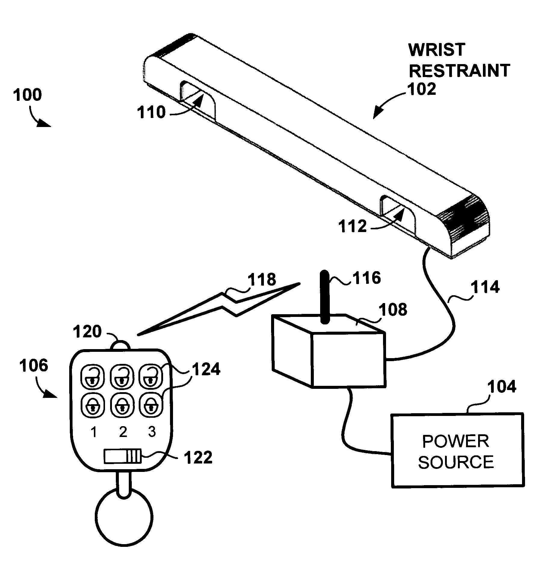
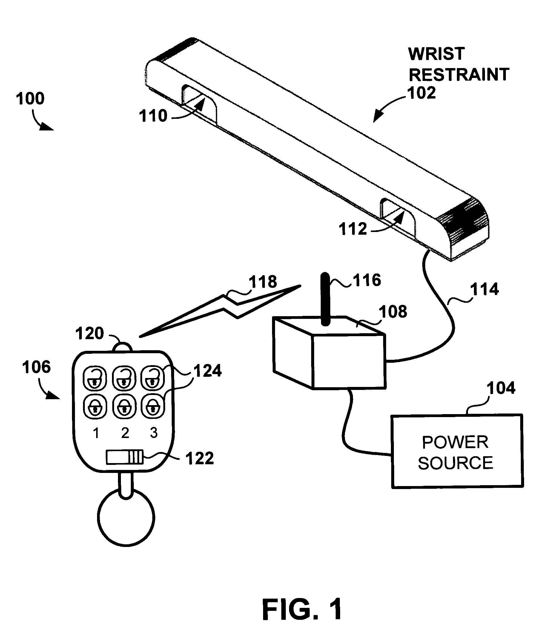
[0026]Turning now to FIG. 1, a preferred...


PUM


Abstract

A restraint system for an appendage includes a clamp assembly and an electromagnet capable of being selectively activated for restraint. The clamp assembly includes a base portion and a restraint structure opposing the base portion. The restraint structure defines an opening for receiving an appendage between the base portion and the restraint structure. When the electromagnet is activated for restraint, the clamp assembly restrains an appendage extending in the opening. Another restraint system includes an inflatable bladder arrangement selectively activated to inflate to a first state and to deflate to a second state. When in the first state, the bladder arrangement defines an opening for passing of an appendage there through; however, when in the second state, the bladder arrangement defines an opening that precludes withdrawal of an appendage extending there through.

Description

CROSS-REFERENCE TO RELATED APPLICATIONS[0001]The present application is a nonprovisional patent application of, and claims priority under 35 U.S.C. § 119(e) to, U.S. provisional patent application Ser. No. 60 / 496,217, filed Aug. 18, 2003, which provisional patent application is incorporated by reference herein. The present application also incorporates herein by reference Disclosure Document No. 525155 received by the OIPE of the USPTO on Jan. 31, 2003, which document has been referenced in the present file history by the applicant.COPYRIGHT STATEMENT[0002]All of the material in this patent document is subject to copyright protection under the copyright laws of the United States and of other countries. The copyright owner has no objection to the facsimile reproduction by anyone of the patent document or the patent disclosure, as it appears in the Patent & Trademark Office file or records but, otherwise, all other copyright rights whatsoever are reserved.BACKGROUND OF THE INVENTION[0...

Claims


Application Information

Patent Timeline
Patent Type & Authority Patents(United States)
IPC IPC(8): E05B75/00B60R21/12B60R99/00E05B47/00E05B51/02
CPCB60R99/00E05B75/00B60R21/12E05B51/02E05B47/00Y10T70/404Y10T70/409Y10T70/7057Y10T292/11
Inventor DIDOMENICO, DENNIS J.
Owner DIDOMENICO DENNIS J
Why Eureka
Try Eureka