Electric cord reel

a technology reels, which is applied in the direction of non-rotary current collectors, cable arrangements between relatively moving parts, coupling device connections, etc., can solve the problems of inconvenient mounting of electric cord reels, inconvenient use, and insufficient space for electric cord reels to be large, so as to achieve greater flexibility of application and use.

Inactive Publication Date: 2006-02-21
WOODHEAD IND INC
View PDF10 Cites 52 Cited by
  • Summary
  • Abstract
  • Description
  • Claims
  • Application Information

AI Technical Summary

Benefits of technology

[0006]It is desirable to mount electric cord reels having a portable outlet receptacle in locations that may have low profiles but which are convenient, and capable of being installed without an inordinate amount of time or expense.
[0011]A series of guide rollers are mounted within the housing for guiding the cord as it is unwound from the reel through the holder and the opening in the front cover of the housing. This enables the cord to be unwound from the reel along a plane generally parallel to the wall, but then the cord is guided and turned approximately 90° by the guide rollers so that as the cable leaves the opening and the holder, it may be pulled in a direction generally perpendicular to the wall and directed over a wide range of angles, laterally or vertically, relative to the opening in the front wall of the housing to provide greater flexibility of application and use.
[0012]A bezel may be provided for use when the unit is mounted within a wall cavity. The bezel may be a plastic frame provided with clips for snapping the bezel on the cover after the unit is mounted within a wall. The bezel covers the inner edge of the mounting opening and overlaps the edge of the front panel of the housing to provide a professional, finished look.

Problems solved by technology

Many prior attempts are not directed to units adapted for semi-permanent mounting on or in a wall.
Wall mounted electric cord reels tend to be bulky, taking up inordinate amounts of space when mounted, particularly when they are mounted to the surface of a wall.
Further, electric cord reels generally are difficult to mount in areas having low ceilings or in otherwise cramped spaces.
It is also a disadvantage of certain wall-mounted cord reels that the cord is unwound in a direction parallel to the wall, with no provision to direct the cord away from the wall toward the area of intended use of the outlet receptacle.

Method used


Image

  • Electric cord reel
  • Electric cord reel
  • Electric cord reel

Examples


Embodiment Construction

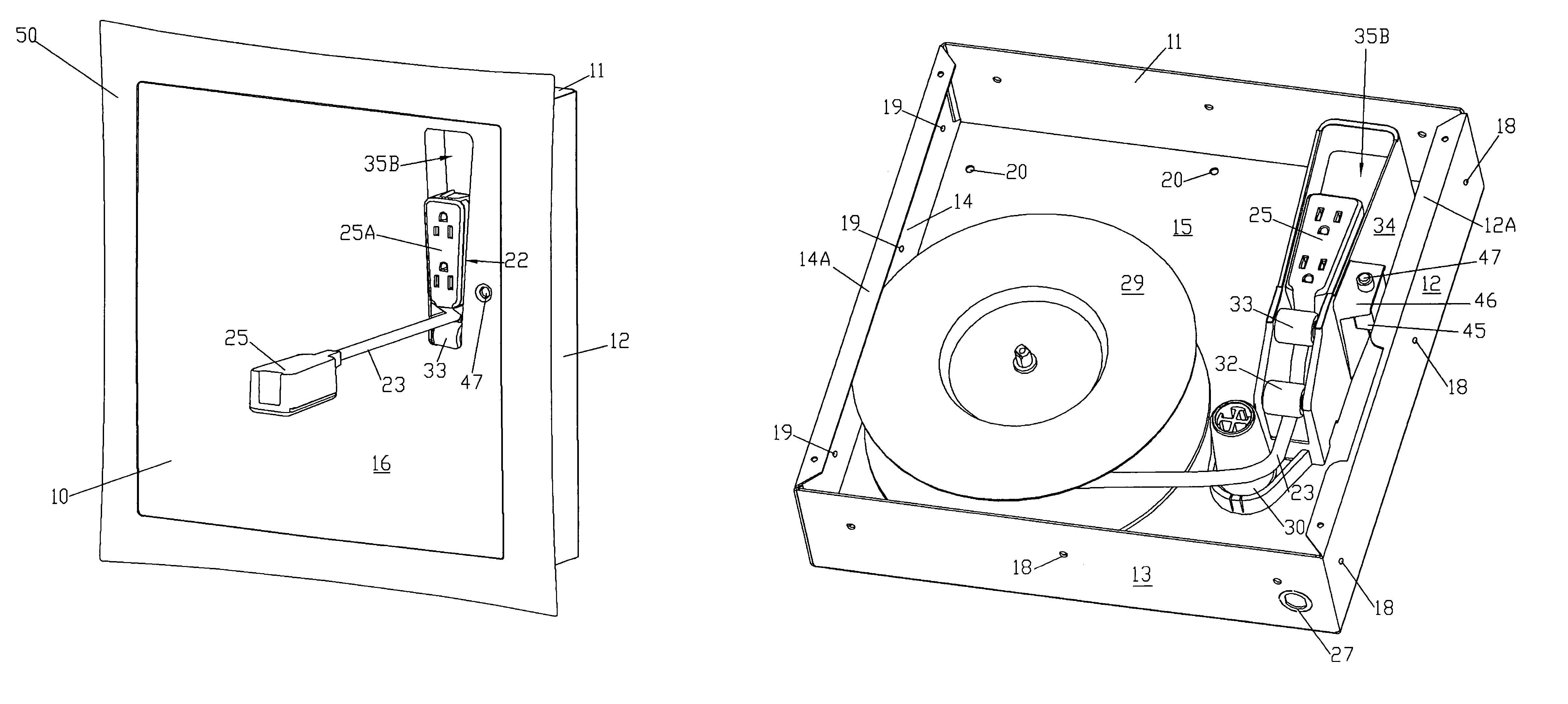
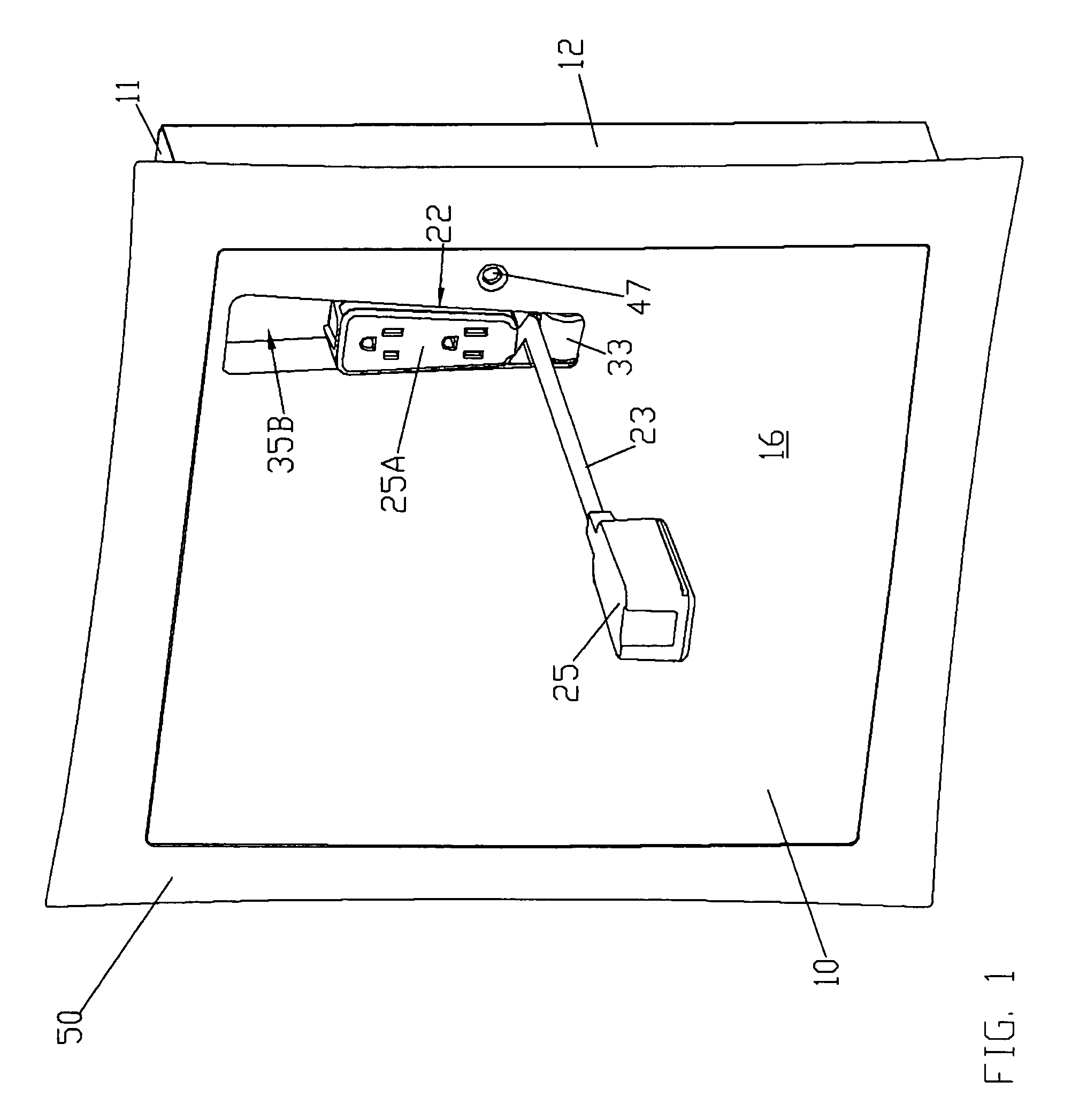
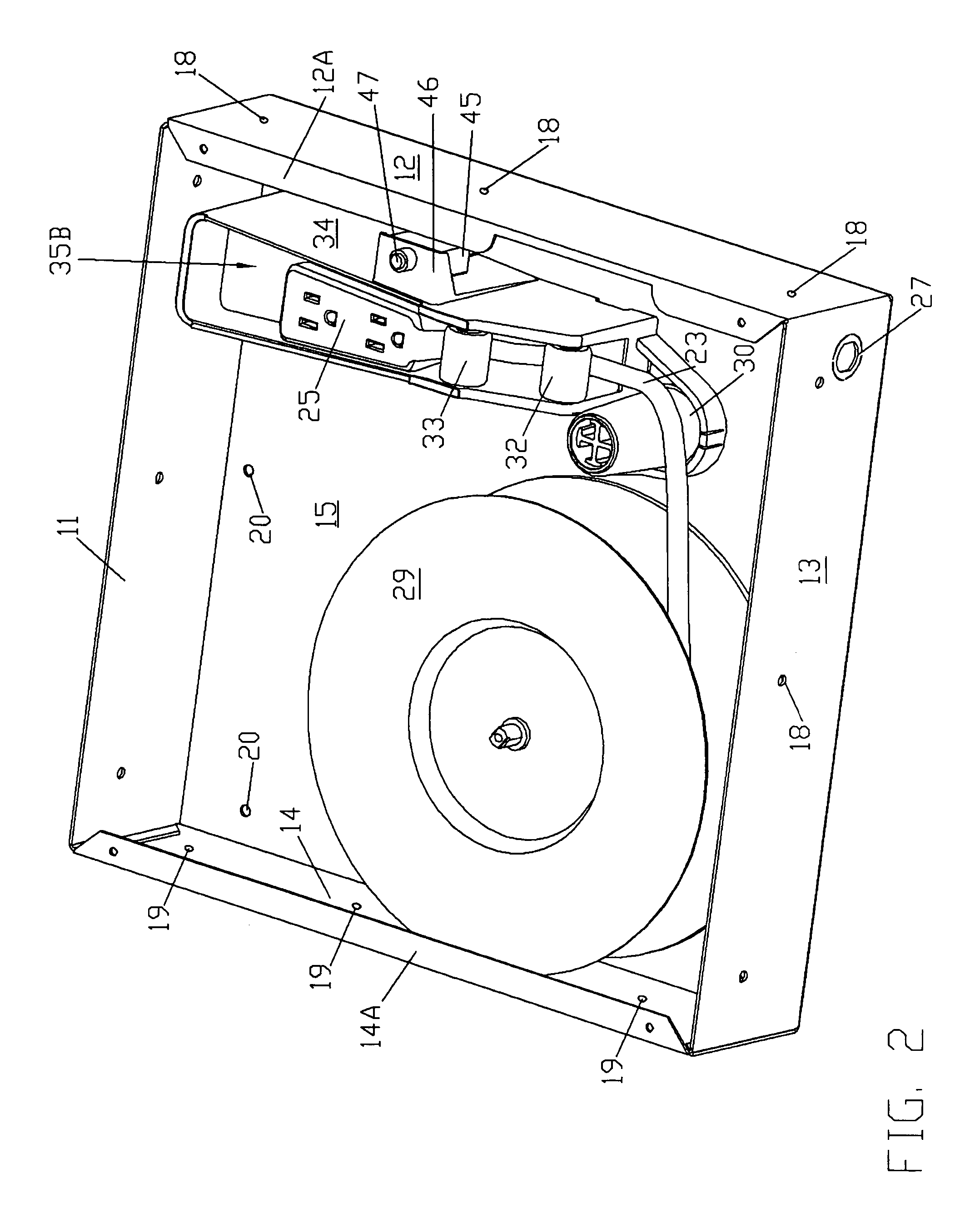
[0020]Referring first to FIG. 1, reference numeral 10 generally designates a housing which may be made of sheet metal and forms an enclosure. The housing 10 has a generally rectangular shape, including a top wall 11, a right side wall 12, a bottom wall 13 (FIG. 2), a left side wall 14, a rear wall 15 and a removable front cover 16. As seen in FIG. 2, the front edges of the side walls 12, 14 may be struck inwardly to provide vertical mounting flanges 12A and 14A for the front cover 16 which may be secured to the flanges 12A, 14A by means of conventional threaded fasteners such as sheet metal screws.

[0021]The spacing of the side walls 12, 14 of the enclosure 10 is such that the side walls may be mounted to opposing surfaces of adjacent studs in a wall; and the depth of the housing (i.e. the distance between rear wall 15 and cover 16) is such that the entire housing may, if desired, be mounted within the wall with the outer surface of the front cover 16 flush with the surface of the wa...


PUM


Abstract

An electrical cord reel includes a metal housing of rectangular shape which is adapted to be mounted set in a wall or on the surface of the wall. The electric cord is mounted on a retractable reel mounted within the housing and may be connected to a source of electricity. An outlet receptacle is mounted to the cord for supplying power to remote locations in the room or work area as the cord is unwound from the reel. A series of guide rollers permit the cord to be paid out in a direction generally perpendicular to the wall, but over a large space for flexible application. The receptacle may be reeled in for storage and used as a wall outlet in the storage position. The receptacle is secured in a recess in the front wall of the housing; and the receptacle may be moved from the storage position to a release position where it is readily removed from the housing for remote use.

Description

RELATED APPLICATION[0001]Applicant claims priority benefit of provisional application No. 60 / 496,959, for “ELECTRIC CORD REEL”, filed on Aug. 21, 2003.FIELD OF THE INVENTION[0002]The present invention relates to electric cord reels wherein the electric cord is equipped with an outlet box or receptacle, for supplying temporary, portable electric power for industrial, commercial or residential use.BACKGROUND AND SUMMARY OF THE INVENTION[0003]Portable electrical outlet receptacle connected to electrical supply cords are widely used to provide a flexible, convenient means for supplying electrical power in a building or room. Sometimes the electrical cord is mounted to a reel so that the length of cord which is not needed for a particular application is stored on the reel, and the cord is completely wound onto the reel after use for storage.[0004]Prior devices include those described in U.S. Pat. Nos. 2,979,576; 3,056,863; 4,114,736; 4,725,697; and 5,236,371. Many prior attempts are not ...

Claims


Application Information

Patent Timeline
Patent Type & Authority Patents(United States)
IPC IPC(8): H01R13/00H02G11/02
CPCH02G11/02
Inventor MACKIN, MICHAEL P.HAGEN, SCOTT A.HILL, TIMOTHY A.ZITO, DONMALEY, GREGORY J.
Owner WOODHEAD IND INC
Why Eureka
Try Eureka