
Opposed piston engine

a piston engine and piston technology, applied in the direction of reciprocating piston engines, positive displacement engines, combustion engines, etc., can solve the problem of not meeting the stringent environmental standards of today

Active Publication Date: 2006-02-28
ENGINUITY POWER SYST INC
View PDF60 Cites 16 Cited by
  • Summary
  • Abstract
  • Description
  • Claims
  • Application Information

AI Technical Summary

Benefits of technology

The invention provides better elements and arrangements in an opposed piston engine that are cheaper, reliable, and work well.

Problems solved by technology

The patent text describes the problem of internal combustion engines using a catal to promote combustion and the use of a two-stroke piston engine with opposed pistons. The text describes various inventions and patents related to this problem. The technical problem addressed by the patent is to provide an improved design for an opposed piston engine that solves the issues of internal combustion and unified piston engines using a catal to promote combustion and the use of a valve control system for controlling the valves. The patent describes various methods and devices related to the art of internal combustion engines and their engines.

Method used


Image

  • Opposed piston engine
  • Opposed piston engine
  • Opposed piston engine

Examples


Embodiment Construction

[0053]The present invention is an opposed piston engine. The invention disclosed herein is, of course, susceptible of embodiment in many different forms. Shown in the drawings and described herein below in detail are preferred embodiments of the invention. It is to be understood, however, that the present disclosure is an exemplification of the principles of the invention and does not limit the invention to the illustrated embodiments.

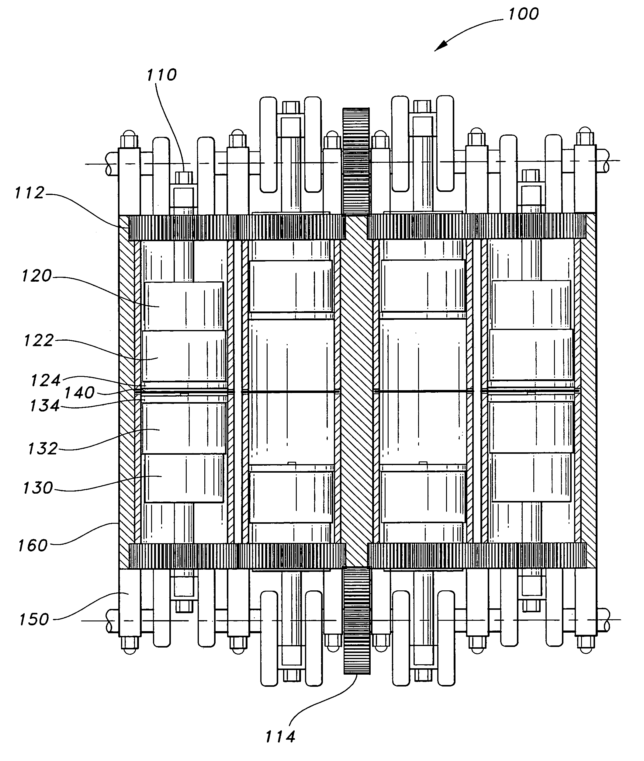
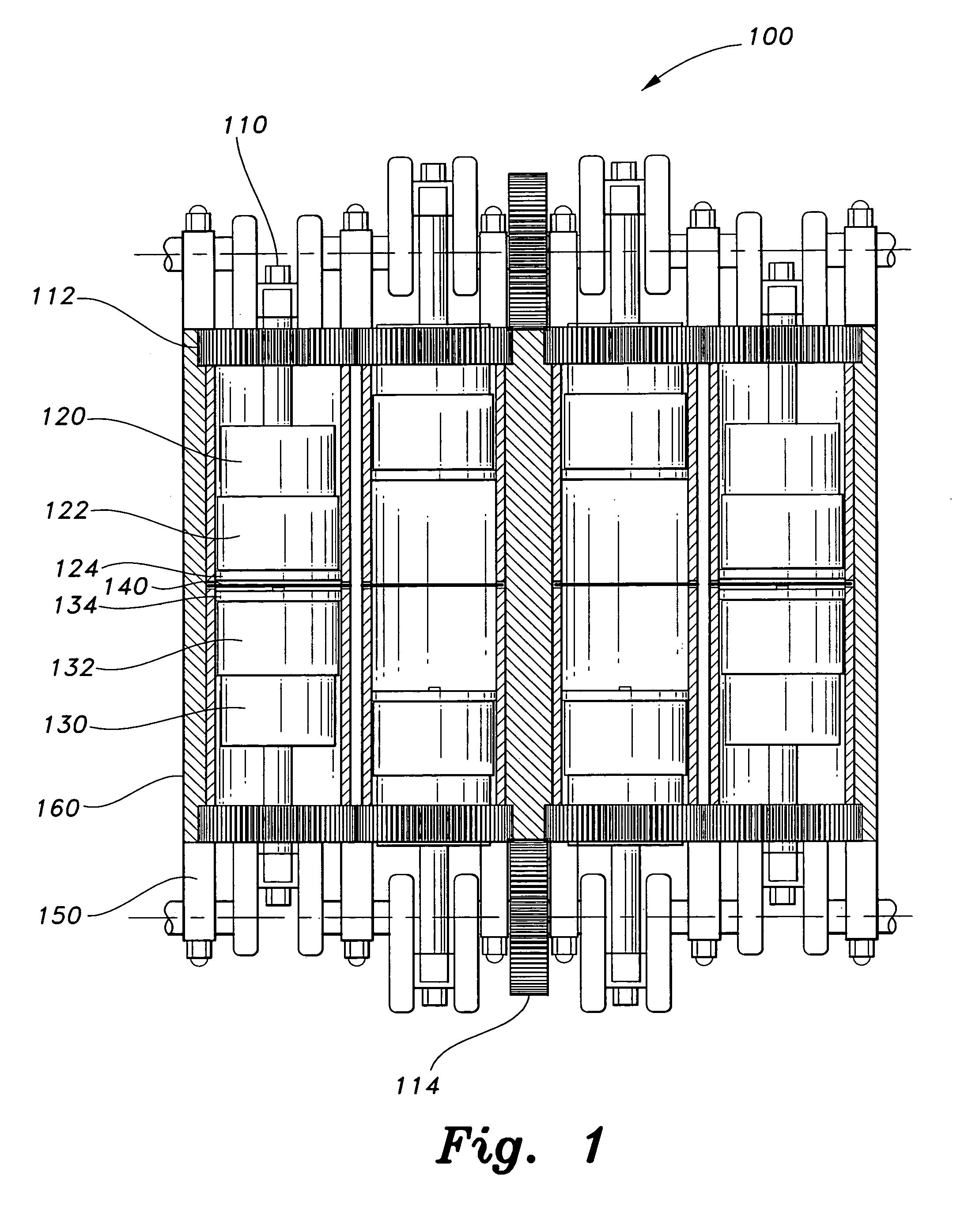
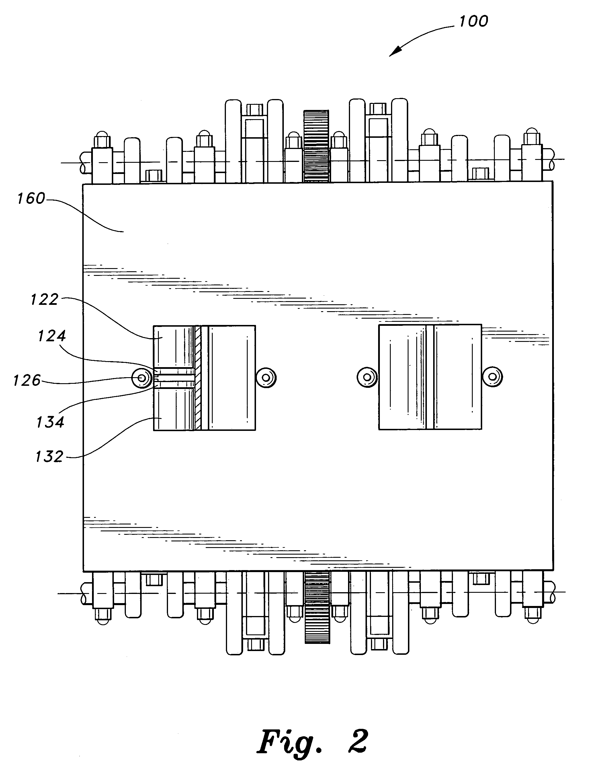
[0054]Referring to the drawings, preferred examples of opposed piston engines according to the present invention are shown in FIGS. 1–2. The opposed piston engine 100 is a four-cycle engine and while it is illustrated with four cylinders configured for rotating, any number of rotating cylinders may be utilized depending on the amount of power desired to be produced by the engine 100. Each cylinder of the engine is associated with a pair of connecting rods 110, a pair of opposing gears 112, opposing first and second pistons 120 and 130 that are each int...


PUM


Abstract

A four-stroke opposed piston engine includes a rotating cylinder with a circumference and an aperture defined through the circumference, first and second opposing pistons, optional first and second opposing cylindrical spacers, first and second opposing piston caps, a spark rod that bisects the cylinder with insulating elements, and a pair of opposing gears.

Description


Claims


Application Information

Patent Timeline
Owner ENGINUITY POWER SYST INC
Learn More