Orthopedic brace having a vacuum chamber and associated methods

a vacuum chamber and orthopedic brace technology, applied in the field of orthopedic braces, can solve the problems of loss of “fit” of the brace, inability to fully understand the value of advice, and often ignored compliance, so as to achieve the effect of preventing the loss of firm conta

Inactive Publication Date: 2006-03-14
VACUITY
View PDF18 Cites 44 Cited by
  • Summary
  • Abstract
  • Description
  • Claims
  • Application Information

AI Technical Summary

Benefits of technology

[0007]The present invention includes a vacuum system and orthopedic brace that effectively prevents the loss of firm contact between the limb and the brace, therefore minimizing, if not completely eliminating the traditional adverse changes.

Problems solved by technology

Otherwise, the inevitable reduction in the degree of swelling that necessarily follows an injury, and / or the associated fluid loss from compression of the brace, produces a loss of “fit” of the brace.
However, compliance is frequently ignored, or the value of the advice is not truly understood.

Method used


Image

  • Orthopedic brace having a vacuum chamber and associated methods
  • Orthopedic brace having a vacuum chamber and associated methods
  • Orthopedic brace having a vacuum chamber and associated methods

Examples


Embodiment Construction

[0012]The present invention will now be described more fully below with reference to the accompanying drawings, in which preferred embodiments of the invention are shown. This invention may include different embodiments and should not be construed as limited to the embodiments set forth below. These embodiments are provided so that the disclosure will be thorough and complete, and will fully convey the scope of the invention to those skilled in the art. The dimensions of layers and regions may be exaggerated in the figures for greater clarity.

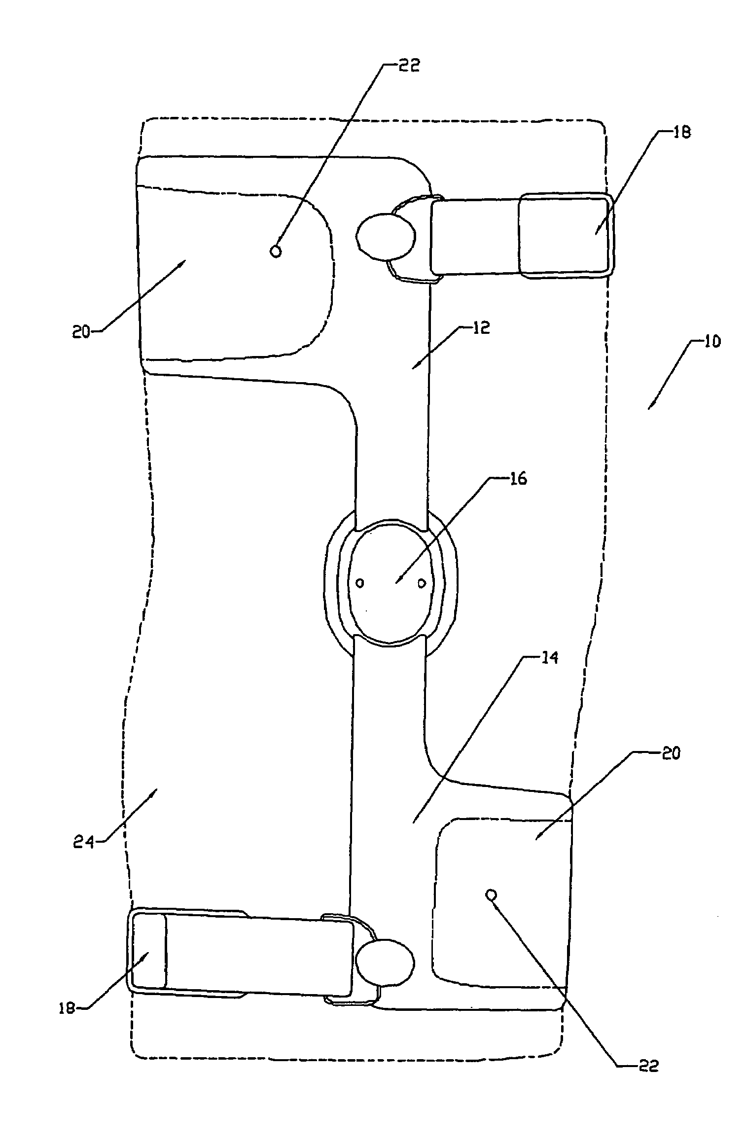
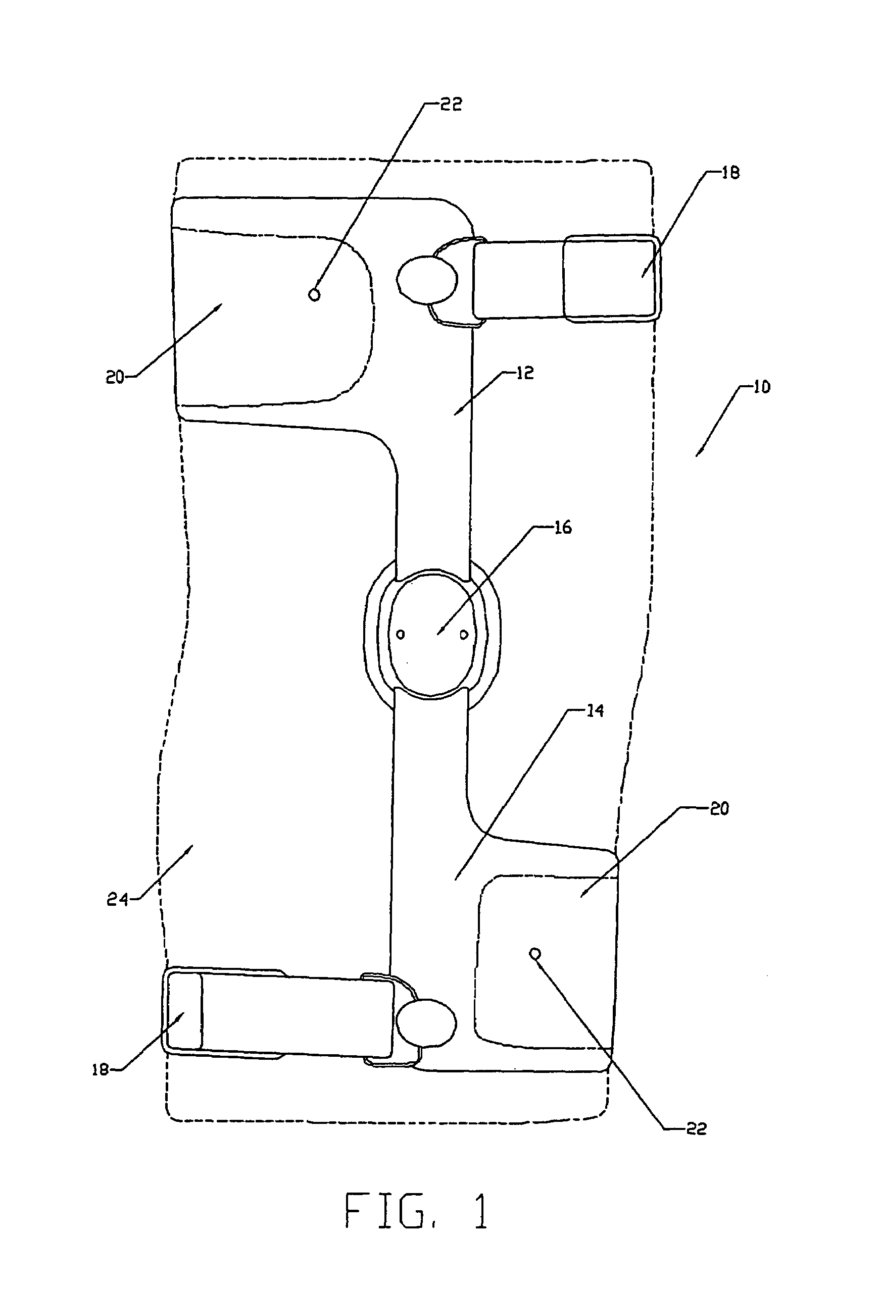
[0013]Referring to FIGS. 1–6, an orthopedic brace 10 is shown, for example, for placement on a leg of a human being. In other words, in this example, the brace 10 is a knee brace, but the invention applies to all types of orthopedic braces including braces for use with feet, ankles, hips, pelvis, back, neck, shoulders, elbows, wrists and hands, for example, as would be appreciated by those skilled in the art.

[0014]FIG. 1 illustrates a preferred...


PUM


Abstract

The vacuum orthopedic brace and method include the use of an inner sleeve or liner, first and second cuffs, and a hinge connecting the cuffs. The cuffs includes a fabric liner or other porous material to act as a wick, and a gasket surrounding the wick material. A valve is preferably provided in the cuff for drawing air from between the cuff and the liner, i.e. to create a vacuum. Furthermore, an external, internal or integrated chamber or rigid reservoir is preferably included, and in communication with the wick filled area between the cuff and liner, to hold a vacuum.

Description

CROSS REFERENCE TO RELATED APPLICATIONS[0001]This application claims the benefit of U.S. Provisional Application No. 60 / 554,042 filed on Mar. 17, 2004.FIELD OF THE INVENTION[0002]The present invention relates to the field of orthopedic braces.BACKGROUND OF THE INVENTION[0003]When a joint has been injured, orthopedic braces often are used to stabilize and protect the joint during the rehabilitation process. Such orthopedic braces may be used for postoperative support and / or to preventive further injury. A typical brace includes rigid structural components dynamically linked together by hinges, such that the axes of the hinges align with the joint being stabilized. Conventionally, the rigid structural components are secured to the body of the wearer above and below the joint by flexible straps to support and protect the joint when the wearer is active.[0004]For example, when the knee is injured, a knee brace can be used to stabilize the knee joint which connects the upper leg or femur...

Claims


Application Information

Patent Timeline
Patent Type & Authority Patents(United States)
IPC IPC(8): A61F5/00A61F5/01A61F5/058
CPCA61F5/05833A61F5/0123
Inventor PATTERSON, WILLIAM S.GAILEY, ROBERTSARMIENTO, AUGUSTOMACKENZIE, MAITLAND C.MCMURRAY, ROY P.
Owner VACUITY
Why Eureka
Try Eureka