Image sensor
a technology of image sensor and led print head, which is applied in the direction of printers, instruments, lenses, etc., can solve the problem that the rod lens array should necessarily be expensive, and achieve the effect of wide reading width and high-quality image reading
- Summary
- Abstract
- Description
- Claims
- Application Information
AI Technical Summary
Benefits of technology
Problems solved by technology
Method used
Image
Examples
embodiment 1
[0027]A first embodiment of the present invention will be hereinafter described.
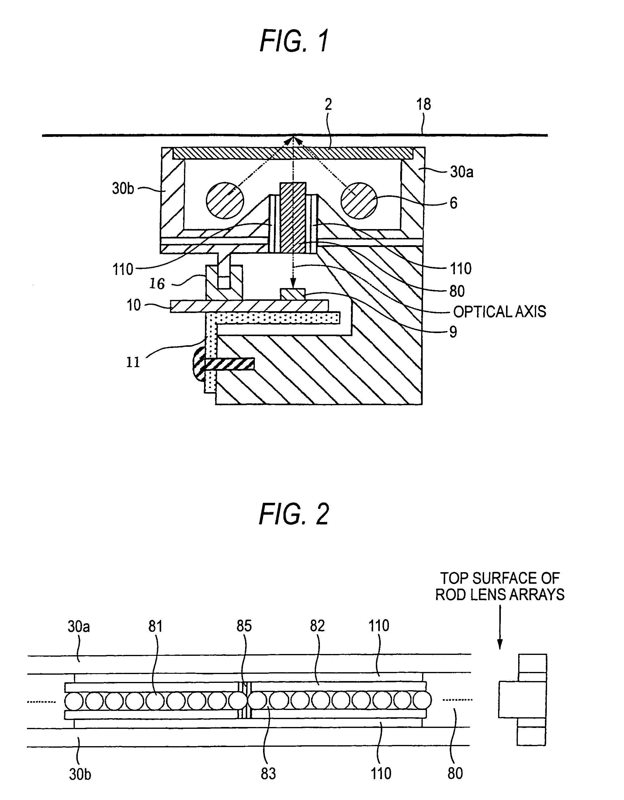
[0028]FIG. 1 is a sectional view showing the configuration of an image sensor according to the first embodiment of the invention. Reference numeral 2 denotes a glass plate having an object (e.g., an original document or a bill) running surface; 6, linear light sources for illuminating an object; 9, light-receiving elements (sensor ICs) for receiving light that is reflected from the object; 10, a sensor substrate on which the light-receiving elements 9 are provided; 11, an L-shaped plate that supports the sensor substrate 10; 16, a shield member for shielding from external light; and 18, the object that is located above the image sensor and runs on the top surface of the glass plate 2 relatively to the image sensor.
[0029]Reference numeral 30 denotes a frame that houses the glass plate 2, the light sources 6, the sensor substrate 10, etc. The frame 30 is composed of a first frame 30a and a second frame 30b...
embodiment 2
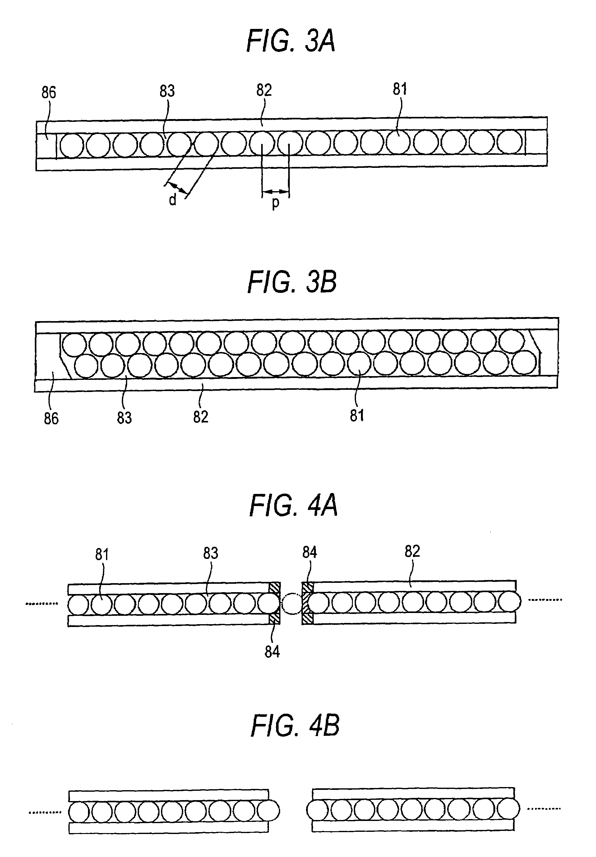
[0062]In the first embodiment, the rod lens arrays 80 are fixed to the frame 30 via the buffer members 110. A second embodiment is directed to a method for fixing the rod lens arrays 80 to the frame 30 more strongly by taking an additional measure.
[0063]The second embodiment of the invention will be described below with reference to FIG. 6. Members in FIG. 6 having the same or corresponding members in FIG. 2 are given the same reference symbols as the latter.
[0064]In FIG. 6, reference numeral 120 denotes an adhesive that is applied, to reinforce the fixing of the rod lens arrays 80 to the frame 30, adjacent to the portions where the rod lens arrays 80 of the image sensor according to the first embodiment are connected to each other by using the sealing agent 85. As shown in FIG. 6, the adhesive 120 is applied to both frames 30a and 30b.
[0065]Although the rod lens arrays 80 are fixed to the frame 30 on both sides by using the continuous double-sided adhesive tapes 110, the double-si...
embodiment 3
[0075]Whereas in the second embodiment the adhesive 120 is applied to the joining portions and their vicinities of the adjoining rod lens arrays 80, a third embodiment is directed to a method of applying an adhesive to portions of the rod lens arrays 80 other than the joining portions and their vicinities.
[0076]The third embodiment of the invention will be described below with reference to FIG. 7.
[0077]In FIG. 7, reference numeral 124 denotes an adhesive that is applied to portions of the rod lens arrays 80 other than the joining portions and their vicinities. The adhesive 124 is applied to both frames 30a and 30b. Although the adhesive 124 is applied to portions of the rod lens arrays 80 near the joining portions, it is not applied to the exposed circumferential surfaces of the end rod lenses 81.
[0078]The sealing agent 85 is mainly intended to provide the light shield effect rather than serves as the bonding means. That is, the sealing agent 85 provides the effect of bonding the ad...
PUM
 Abstract
Description
Claims
Application Information
 - R&D
- Intellectual Property
- Life Sciences
- Materials
- Tech Scout
- Unparalleled Data Quality
- Higher Quality Content
- 60% Fewer Hallucinations
Browse by: Latest US Patents, China's latest patents, Technical Efficacy Thesaurus, Application Domain, Technology Topic, Popular Technical Reports.
© 2025 PatSnap. All rights reserved.Legal|Privacy policy|Modern Slavery Act Transparency Statement|Sitemap|About US| Contact US: help@patsnap.com


