Image sensor

a technology of image sensor and led print head, which is applied in the direction of printers, instruments, lenses, etc., can solve the problem that the rod lens array should necessarily be expensive, and achieve the effect of wide reading width and high-quality image reading

Active Publication Date: 2005-07-28
MITSUBISHI ELECTRIC CORP
View PDF4 Cites 17 Cited by
  • Summary
  • Abstract
  • Description
  • Claims
  • Application Information

AI Technical Summary

Benefits of technology

[0016] With this configuration, the inclination of each rod lens array can be corrected so that its optical axis coincides with a prescribed optical axis by pushing the rod lens array with a screw from outside the frame. Therefore, the image forming position of each rod lens array can be adjusted with respect to an original document and the light-receiving elements, and high-quality image reading that is free of image blurring can be attained over a wide reading width.

Problems solved by technology

A problem arises that such a rod lens array should necessarily be expensive.

Method used


Image

  • Image sensor
  • Image sensor
  • Image sensor

Examples


embodiment 1

[0027] A first embodiment of the present invention will be hereinafter described.

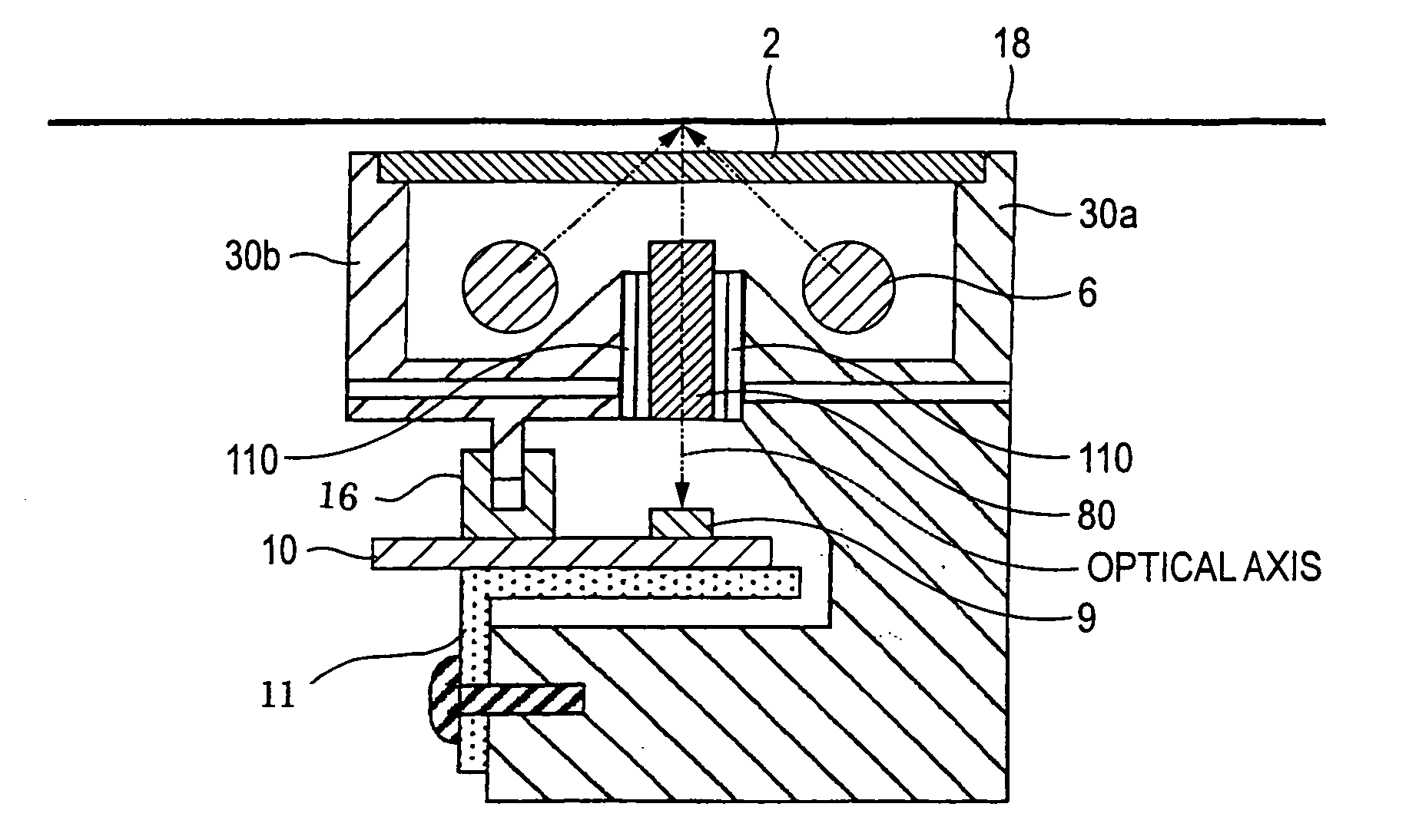
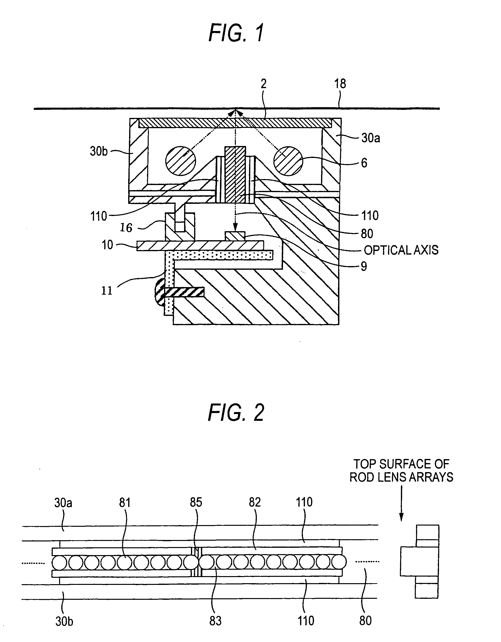
[0028]FIG. 1 is a sectional view showing the configuration of an image sensor according to the first embodiment of the invention. Reference numeral 2 denotes a glass plate having an object (e.g., an original document or a bill) running surface; 6, linear light sources for illuminating an object; 9, light-receiving elements (sensor ICs) for receiving light that is reflected from the object; 10, a sensor substrate on which the light-receiving elements 9 are provided; 11, an L-shaped plate that supports the sensor substrate 10; 16, a shield member for shielding from external light; and 18, the object that is located above the image sensor and runs on the top surface of the glass plate 2 relatively to the image sensor.

[0029] Reference numeral 30 denotes a frame that houses the glass plate 2, the light sources 6, the sensor substrate 10, etc. The frame 30 is composed of a first frame 30a and a second frame...

embodiment 2

[0062] In the first embodiment, the rod lens arrays 80 are fixed to the frame 30 via the buffer members 110. A second embodiment is directed to a method for fixing the rod lens arrays 80 to the frame 30 more strongly by taking an additional measure.

[0063] The second embodiment of the invention will be described below with reference to FIG. 6. Members in FIG. 6 having the same or corresponding members in FIG. 2 are given the same reference symbols as the latter.

[0064] In FIG. 6, reference numeral 120 denotes an adhesive that is applied, to reinforce the fixing of the rod lens arrays 80 to the frame 30, adjacent to the portions where the rod lens arrays 80 of the image sensor according to the first embodiment are connected to each other by using the sealing agent 85. As shown in FIG. 6, the adhesive 120 is applied to both frames 30a and 30b.

[0065] Although the rod lens arrays 80 are fixed to the frame 30 on both sides by using the continuous double-sided adhesive tapes 110, the dou...

embodiment 3

[0075] Whereas in the second embodiment the adhesive 120 is applied to the joining portions and their vicinities of the adjoining rod lens arrays 80, a third embodiment is directed to a method of applying an adhesive to portions of the rod lens arrays 80 other than the joining portions and their vicinities.

[0076] The third embodiment of the invention will be described below with reference to FIG. 7.

[0077] In FIG. 7, reference numeral 124 denotes an adhesive that is applied to portions of the rod lens arrays 80 other than the joining portions and their vicinities. The adhesive 124 is applied to both frames 30a and 30b. Although the adhesive 124 is applied to portions of the rod lens arrays 80 near the joining portions, it is not applied to the exposed circumferential surfaces of the end rod lenses 81.

[0078] The sealing agent 85 is mainly intended to provide the light shield effect rather than serves as the bonding means. That is, the sealing agent 85 provides the effect of bonding...


PUM


Abstract

An image sensor is provided with a light source for illuminating an original document with light, a plurality of rod lens arrays arranged continuously and connected to each other in such a manner that end rod lenses located at the ends of the rod lens arrays are in contact with each other among rod lenses for forming images of light reflected from the original document, a sealing agent that fills in each of gaps between the end rod lenses, light-receiving elements for receiving image-forming light produced by the rod lenses over a prescribed reading width, and a frame to which the rod lens arrays are fixed via buffers over the prescribed reading width. A long image sensor can be realized at a low cost by using short, general-purpose rod lens arrays.

Description

BACKGROUND OF THE INVENTION [0001] 1. Field of the Invention [0002] The present invention relates to an image sensor and an LED print head that are used in image input devices, image writing devices, etc. In particular, the invention relates to a long contact image sensor incorporating a rod lens array. [0003] 2. Description of the Related Art [0004] An image sensor incorporating a rod lens array that is interposed between first and second frames is disclosed in FIG. 1 of JP-A-2002-218159 as a device incorporating a rod lens array. [0005] Further, a writing device in which three rod lenses are packaged integrally by a package case and a device body is disclosed in FIG. 1 of JP-A-2001-150729. [0006] In FIG. 1 of JP-A-2002-218159, reference numeral 1 denotes an image sensor; 2, a glass plate, 3; a frame, 6; light sources; 8, a rod lens array consisting of a plurality of rod lenses arranged in one direction; 9, light-receiving elements; 10, a sensor substrate; and 18, an original docum...

Claims


Application Information

Patent Timeline
Patent Type & Authority Applications(United States)
IPC IPC(8): G03B27/50G02B3/00H01L27/00H04N1/028H04N1/40
CPCG02B3/0037G02B3/0087G02B3/0075
Inventor MATSUMOTO, TOSHIO
Owner MITSUBISHI ELECTRIC CORP
Why Eureka
Try Eureka