Active sawguide assembly and method

a sawguide and active technology, applied in the field of active sawguide package system, can solve the problems of poor strength characteristics of heartwood, unsuitability for structural grade timber, and uneven surface, and achieve the effect of most recovery of structural grade wood

Inactive Publication Date: 2006-03-21
USNRKOCKUMS CANCAR
View PDF9 Cites 3 Cited by
  • Summary
  • Abstract
  • Description
  • Claims
  • Application Information

AI Technical Summary

Benefits of technology

[0018]By providing a gang saw with two separately controlled arrays of saws capable of independently following a different optimized path, the sapwood of fast growing species may be optimized on both sides of a two-sided cant to avoid inclusion of heartwood and thereby achieve the most recovery of structural grade wood.

Problems solved by technology

One of the problems with these trees is that the heartwood has poor strength characteristics and is unsuitable for structural grade timber.
Both the Kenyan and Lundstrom devices use mechanical means to center the cant during curve sawing and thus disparities on the surface of the cant such as scars, knots, branch stubs and the like tend to disturb the machining operation and produce a “wave” in the cant.
Also, cants subjected to these curve sawing techniques tend to have straight sections on each end of the cant.
It has also been found that full taper curve sawing techniques, because the cut follows a line approximately parallel to the convex or concave surface of the cant, can only produce lumber that mimics these surfaces, and the shape produced may be unacceptably bowed.
Arc sawing techniques solve the mechanical centering problems encountered with curve sawing but limit the recovery possible from a cant by constraining the cut solution to a radial form.

Method used


Image

  • Active sawguide assembly and method
  • Active sawguide assembly and method
  • Active sawguide assembly and method

Examples


Embodiment Construction

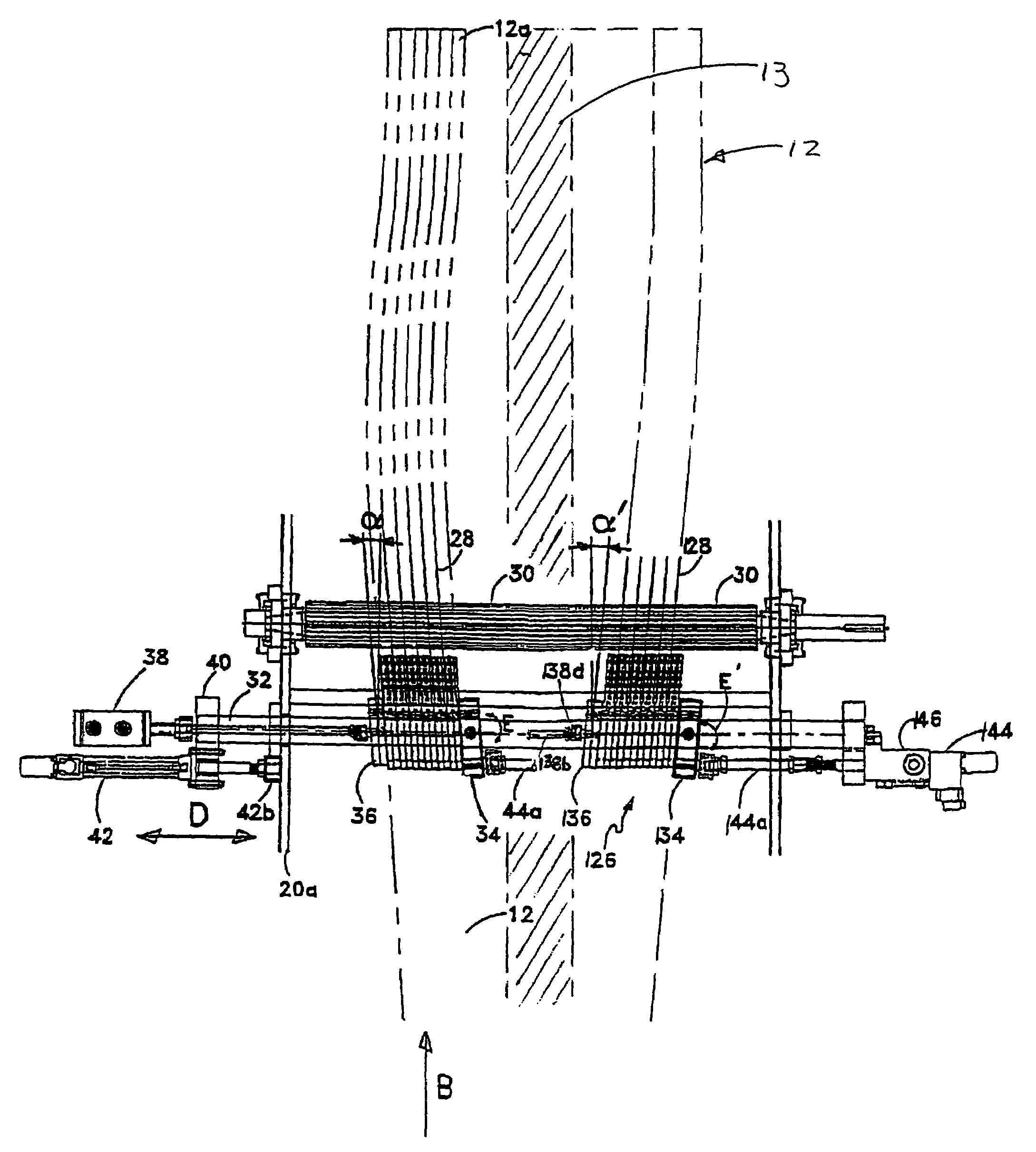
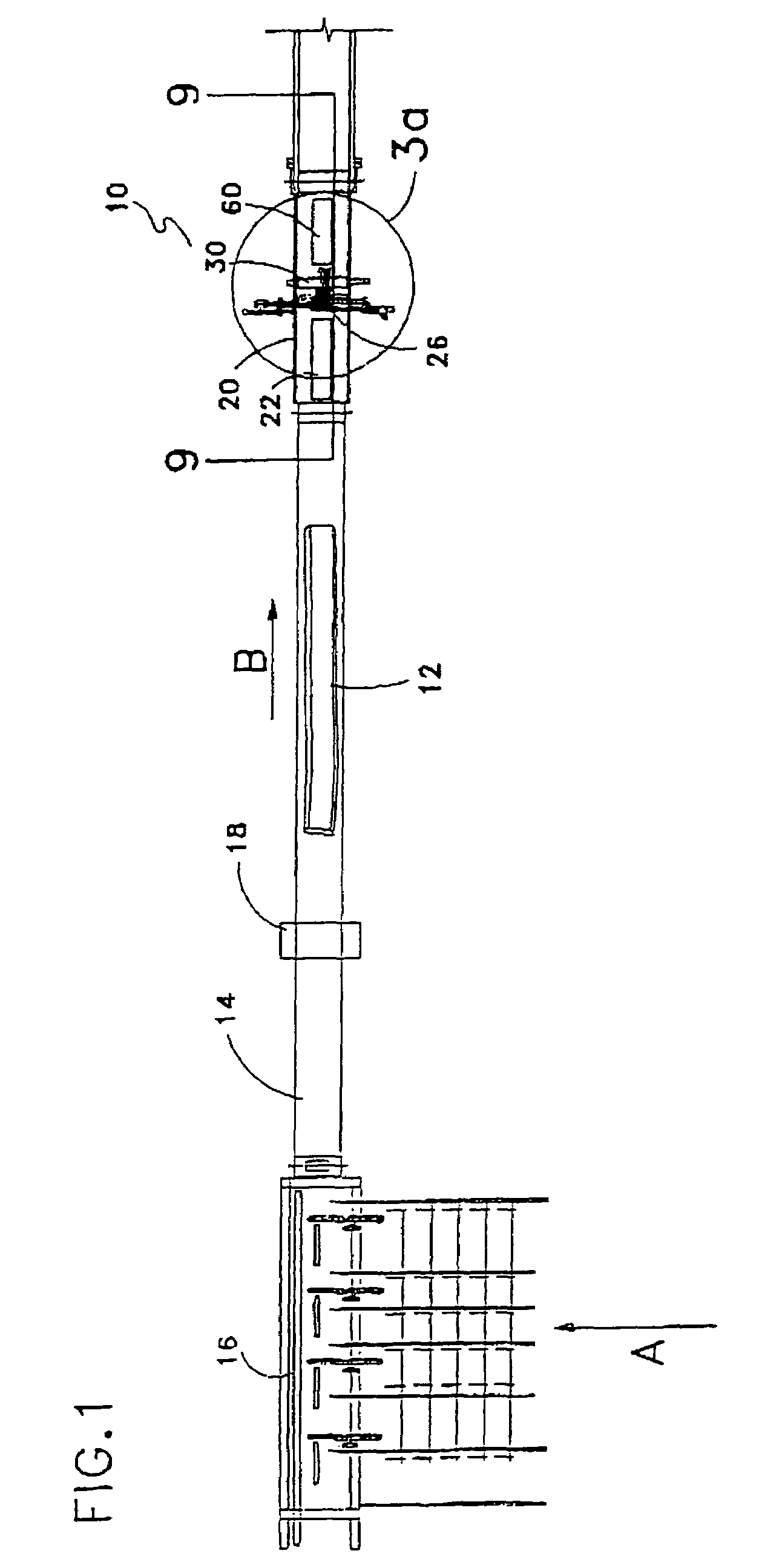
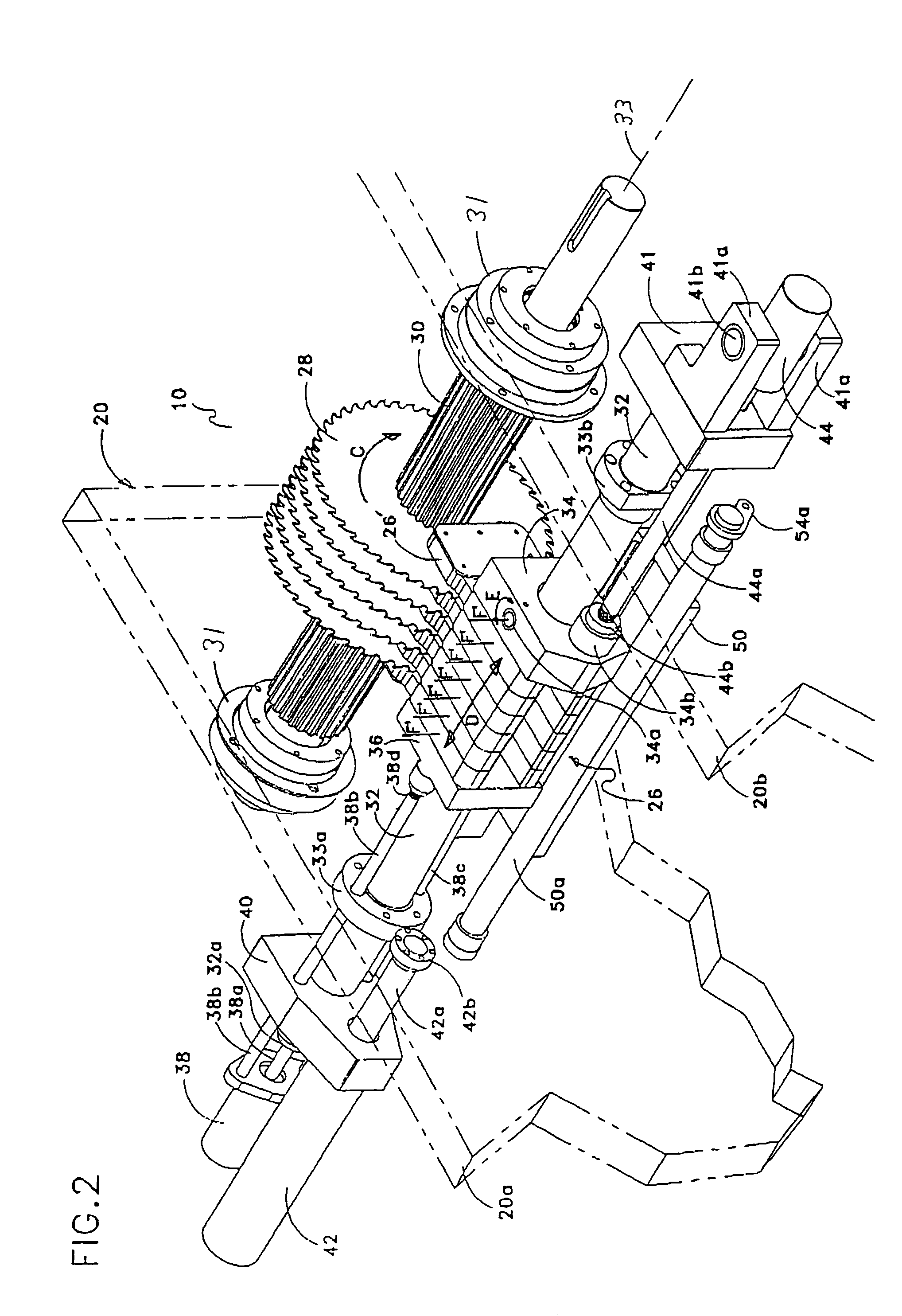
[0040]Referring to the drawing figures wherein similar characters of reference represent corresponding parts in each view, the active sawguide assembly of the present invention is generally indicated by the reference numeral 10.

[0041]A workpiece 12 is fed transversely from the mill in direction A and is directed onto a lineal transfer 14 and positioned against a fixed fence 16 or other positioning means, for roughly or approximately centering the workpiece on the lineal transfer. Once workpiece 12 is roughly centered on lineal transfer 14 it is translated lineally in direction B through a lineal scanner 18 towards sawbox 20. Scanner 18 scans workpiece 12. Once through the scanner workpiece 12 is translated onto an infeed sharpchain transfer 22 positioned within the infeed area of sawbox 20. As best seen in FIG. 9 a plurality of overhead driven press rolls 24 are located above infeed sharp chain transfer 22. Press rolls 24 press down on workpiece 12 to feed workpiece 12 straight into...


PUM

PropertyMeasurementUnit
volumeaaaaaaaaaa
strengthaaaaaaaaaa
lengthaaaaaaaaaa

Abstract

A sawguide assembly includes a plurality of sets of sawguides, the sawguides within each set positioned adjacent to one another to create an array of laterally-abutting sawguides. Corresponding sawguide biasing assemblies bias the sawguides in each set against one another. The arrays are supported for independent movement along a lateral path generally parallel to the axis of the arbor. Lateral drivers are used to move each array in unison along the lateral path but independent of the other arrays. A sawguide array skewing assembly couples the sawguides of each array to one another so that the sawguides can be pivoted in unison about their respective pivot axes by a corresponding skewing driver.

Description

CROSS REFERENCE TO RELATED APPLICATION[0001]This is a continuation-in-part of Divisional patent application Ser. No. 10 / 621,938 filed Jul. 17, 2003, now U.S. Pat. No. 6,877,411 which is a divisional application of U.S. patent application Ser. No. 09 / 792,891 filed Feb. 23, 2001, now U.S. Pat. No. 6,612,216 which claims the benefit of Provisional Patent Application No. 60 / 184,422 filed Feb. 23, 2000.FIELD OF THE INVENTION[0002]This invention relates to a method and an apparatus for straight or curve sawing workpieces such as cants or timbers or lumber, and in particular relates to an active sawguide package system which is constantly adjusted to a target line during sawing, for curve sawing workpieces according to an optimized profile.BACKGROUND OF THE INVENTION[0003]It is known that in today's competitive sawmill environment, it is desirable to quickly process straight or non-straight cants so as to recover the maximum volume of cut lumber possible from the cant. For non-straight can...

Claims


Application Information

Patent Timeline
Patent Type & Authority Patents(United States)
IPC IPC(8): B23D45/10B27B5/36B27B7/04
CPCB27B7/04B27B5/36Y10T83/155Y10T83/659Y10T83/7818Y10T83/7876Y10T83/869Y10T83/8878Y10T83/888
Inventor MCGEHEE, RONALD W.BURNS, JEFFREY T.MITCHELL, RORY M.STROUD, BRIAN T.
Owner USNRKOCKUMS CANCAR
Why Eureka
Try Eureka