
Container

a container and container base technology, applied in the field of containers, can solve the problems of lack of stability and strength, less rigid container, and large load on the container base, and achieve the effect of more volum

Inactive Publication Date: 2006-03-28
REHRIG PACIFIC CO INC
View PDF79 Cites 42 Cited by
  • Summary
  • Abstract
  • Description
  • Claims
  • Application Information

AI Technical Summary

Benefits of technology

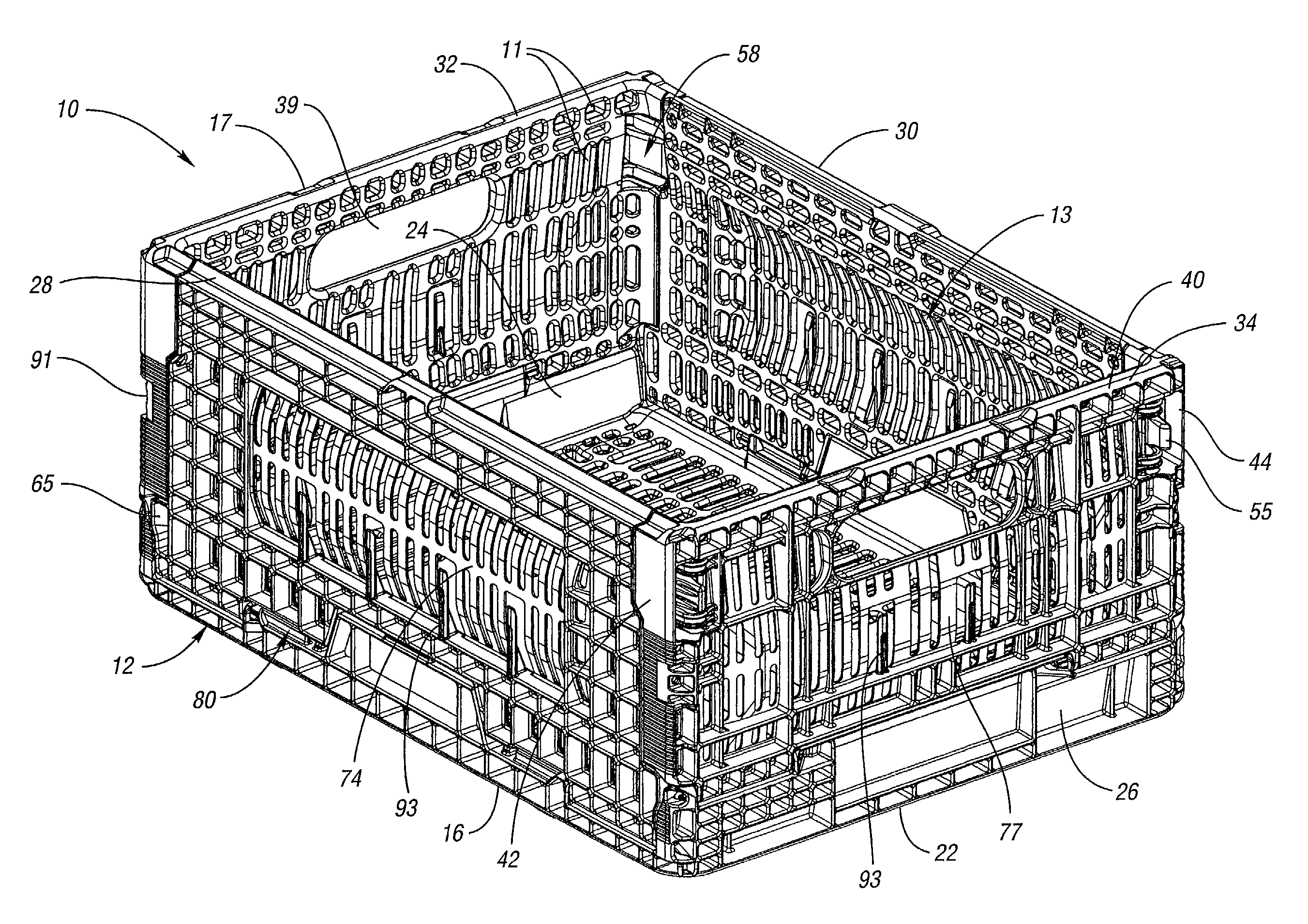
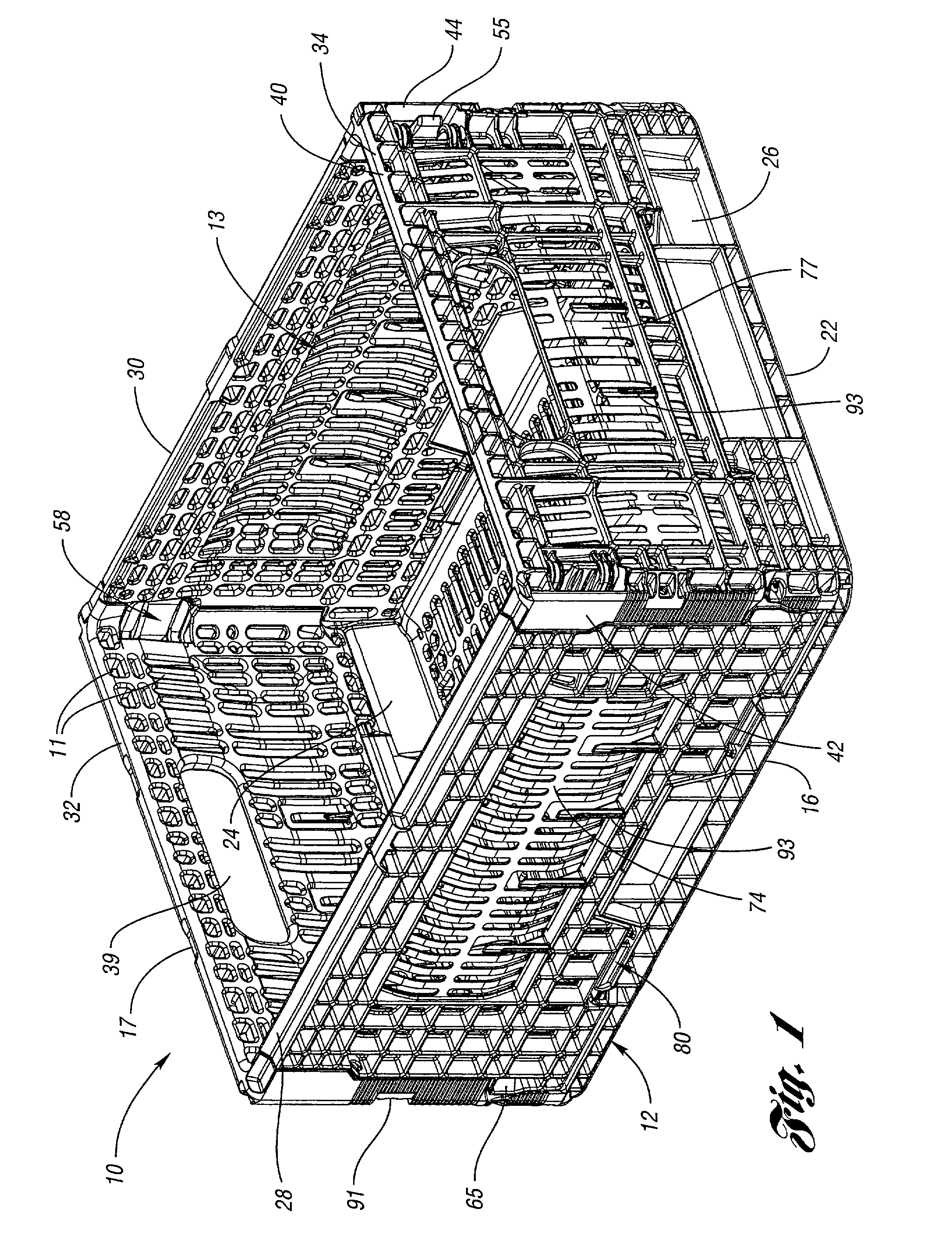
[0010]It is an object of the present invention to provide a collapsible container which has improved strength and top loading stability.
[0011]Moreover, it is an object according to the present invention to provide a collapsible display container which is cost effective to manufacture and efficient to assemble.
[0012]Further, it is another object according to the present invention to provide a collapsible display container which is capable of nesting with the like containers when in a collapsed position, and is also capable of stacking with like containers when in the assembled position.

Problems solved by technology

However, for an assembled container during use, this corner system results in a less rigid container due to the corners being subjected to torsional and other bending forces during use.
Moreover, the base of the container is subject to a relatively large amount of load when the container is filled and may frequently be lacking in the area of stability and strength.
Because there exists a gap between the short walls when folded, a container stacked thereupon is not fully supported in the area of the gap.
Also, because one container rests upon the walls of another container, any transfer of top load forces is transferred through the walls, which may reduce the durability of the container.
Such palletizing of the containers is often done automatically by machinery which may improperly position the straps, or subject the containers to unnecessary stress.
Many containers also have a limited width or volume efficiency due to the way they are constructed, as well as due to their intended use.
For example, produce such as bananas may require special handling because of their shape and as well as their capacity to be bruised.
Unfortunately, the same containers used to transport produce such as bananas are also used to transport other non-perishable objects.
Accordingly, in some instances, such produce may be subject to less than ideal handling and transport conditions.

Method used


Image

  • Container
  • Container
  • Container

Examples


second embodiment

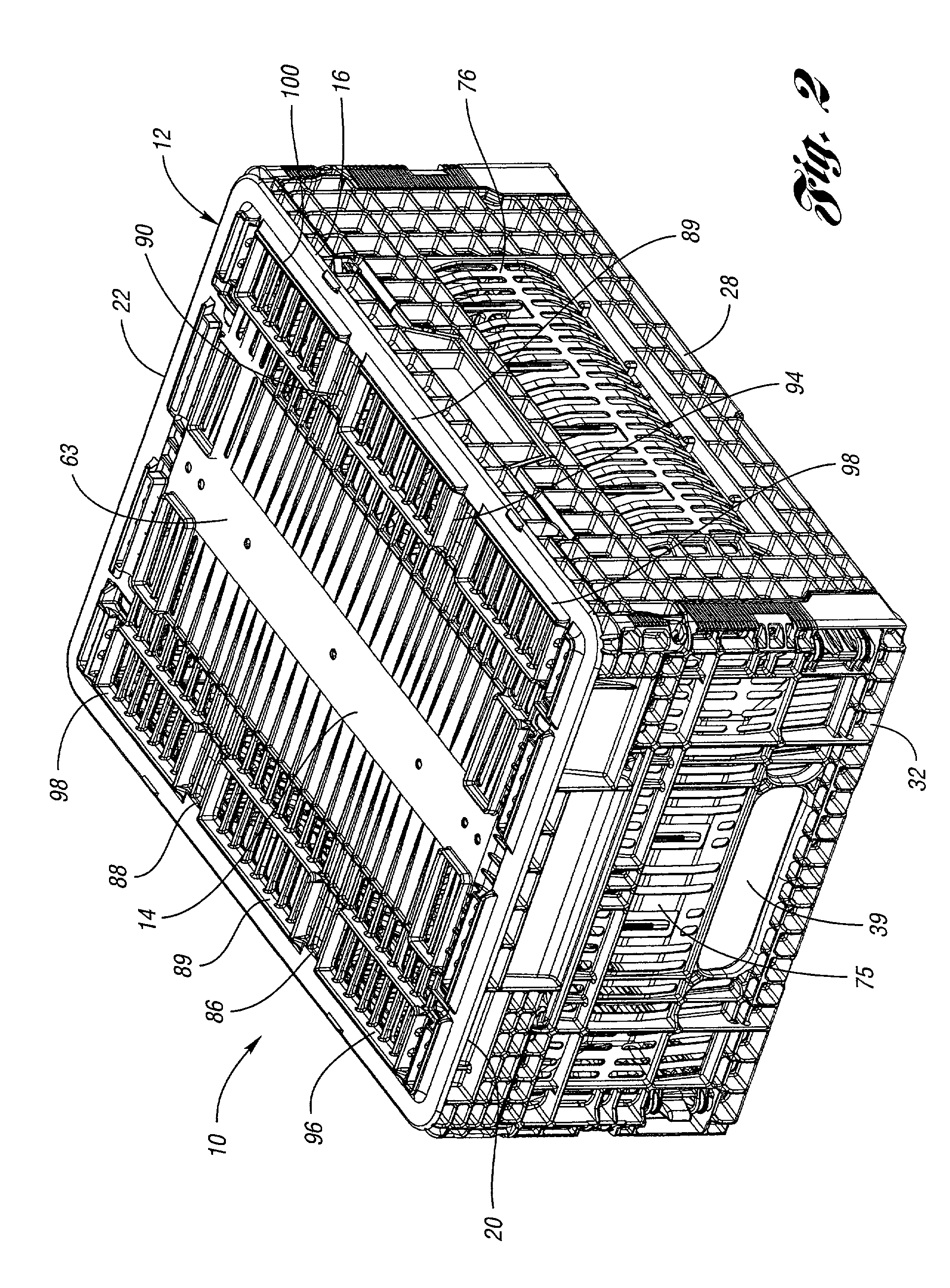
[0106]FIG. 26 illustrates a top perspective view of a base 112 of container 110, while FIG. 28 is a bottom perspective view of base 112. FIG. 27 is a cross-sectional view taken along the line 27—27 of FIG. 26. Referring to these drawings, base 112 has a bottom panel 114 which includes at least one curved portion—and preferably two curved portions 141, 143—which extend between edges 116 and 118, the curved portions being bowed upward with a relatively slight arcuate shape, instead of having a typical flat profile. This curved portion is illustrated to be wave-like or sinusoidal, and disposed in the central portion of bottom panel 114. This bowed feature of bottom panel 114 serves to add stability to the container and augment the life of the container, as well as provide protection to the contents of containers stacked therebelow. Particularly, when container 110 is filled or has goods placed therein, the weight of the goods will exert load upon bottom panel 114. Under this load, the ...

first embodiment

[0107]FIG. 29 is a side elevational view of container 110 in an assembled orientation, as in FIG. 25. As illustrated, like the first embodiment, container 110 also includes notch 191 for the palletizing straps, and further includes the portion of side walls 128, 130 which extends into and mates with a corresponding recess 146 in the corner region, proximate the corner hinge connection. FIG. 30 is an end elevational view again illustrating features of end wall 134.

[0108]FIG. 31 illustrates container 110 in an inwardly folded orientation. As FIGS. 31 and 32 indicate, the design according to the present invention allows container 110 to be compactly folded for storage and transport. In this orientation, side walls 128, 130 are pivoted inward via hinging mechanisms 180 and folded in a layered fashion on top of bottom panel 114. FIG. 32 illustrates that side walls 128 and 130 are folded first, and subsequently, end walls 132,134 are folded inward on top of side walls 128, 130 via hinging...

third embodiment

[0120]Accordingly, base 310 is a flexible platform or member which is adapted to conform generally to the natural shape of the banana bunch 300 or other produce or objects resting thereupon. FIG. 39 illustrates the general mating of the base 310 and the objects 300. Such a base 310 supports bananas 300 and also allows for bananas 300 to be shipped “hands-up” referring to the banana bunch's natural shape, as illustrated in FIGS. 47, 48, and 49. In the “hands-up” orientation, flexible base 310 may easily conform and mate with the natural shape of the bananas. In many cases, retailers often display bananas in the “hands-up” position. Therefore, these same retailers may desire that the bananas be shipped in the “hands-up” orientation in the container, which allows them to arrive display-ready. However, as represented by container 210, bananas may otherwise usually shipped in a “hands-down” orientation, resting on their tips 302 and crowns 304. Of course, as previously noted, flexible ba...


PUM


Abstract

A container adapted for storing and transporting an item having a shape includes a flexible bottom panel which has an upper surface upon which the item is supported, and a lower surface having a plurality of parallel, spaced apart ribs with a relatively thin-walled section between each adjacent pair of ribs. The flexible bottom panel is adapted to conform to the shape of the item resting thereon.

Description

[0001]This application is a continuation of Ser. No. 09 / 549072 filed Apr. 16, 2000, now U.S. Pat. No. 6,386,388.TECHNICAL FIELD[0002]This invention relates to a container adapted for storing, transporting, and displaying produce items and other goods.BACKGROUND ART[0003]Collapsible containers and crates are commonly used to transport and store a variety of items. Such crates are typically formed of injection molded plastic and are frequently adapted to receive perishable food items, such as produce. When assembled, such containers are rectangular in shape, and have a flat base surrounded by four upstanding flat side panels which are joined to the flat base. When the containers are not in use, the collapsible feature of the containers allows the containers to be folded or otherwise reduced in size, thereby providing a desired compact size when storage space is minimal.[0004]In such collapsible containers, side wall edges are normally joined in the corners. However, for an assembled c...

Claims


Application Information

Patent Timeline
IPC IPC(8): B65D6/18B65D1/22B65D6/22B65D85/34
CPCB65D11/1833B65D11/20B65D85/34
Inventor OVERHOLT, TRENTON M.
Owner REHRIG PACIFIC CO INC
Learn More