Collapsible container for liquids

a container and liquid technology, applied in the field of liquid storage containers, can solve the problems of bag collapse upon itself, waste of liquid remaining in the bag, and the addition of evacuation strips to the bag manufacturing process,

Inactive Publication Date: 2006-03-28
DR PEPPER SEVEN UP
View PDF86 Cites 29 Cited by
  • Summary
  • Abstract
  • Description
  • Claims
  • Application Information

AI Technical Summary

Benefits of technology

[0009]Accordingly, this invention is directed to an improved collapsible bag having a spout and one or more grooves on the interior surface of a wall of the bag. The grooves, which are integral to a wall of the bag rather than on a separate evacuation strip, are in liquid communication with the spout and are sized such that the opposing wall of the bag is not completely forced into the grooves under the suction of conventional pumps which are used to withdraw the liquid from the bag. Thus, the grooves enable substantially complete withdrawal of the liquid from the bag without the use of an evacuation strip. Additionally, the present invention may be used in any orientation and does not require a slanted rack. Although the primary intended application of the present invention is in bag-in-box packages for containing and dispensing beverages, this invention may also be used to advantage in other liquid dispensing applications.

Problems solved by technology

One of the problems associated with such bag-in-box packages is that the bag collapses upon itself as the liquid is withdrawn, which tends to create pockets of liquid that are isolated from the spout and cannot be withdrawn from the bag.
Thus, the residual portion of liquid remaining in the bag is wasted.
However, the evacuation strip adds an extra complication to the bag manufacturing process.
However, the need for a special slanted rack is a disadvantage to such an arrangement.
Another disadvantage is the required orientation of the spout in a particular position, namely, at the lowest possible point.

Method used


Image

  • Collapsible container for liquids
  • Collapsible container for liquids
  • Collapsible container for liquids

Examples


Embodiment Construction

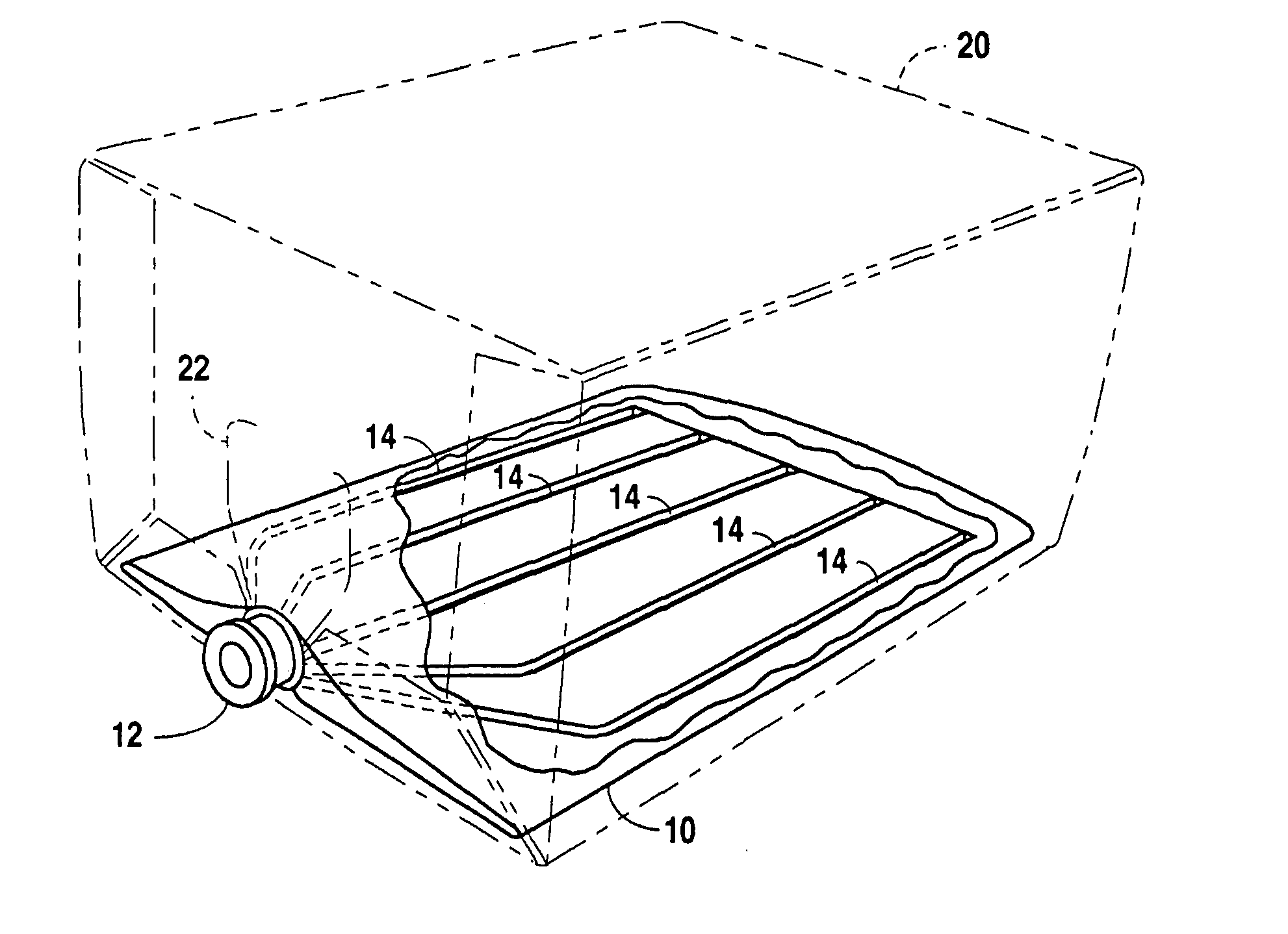
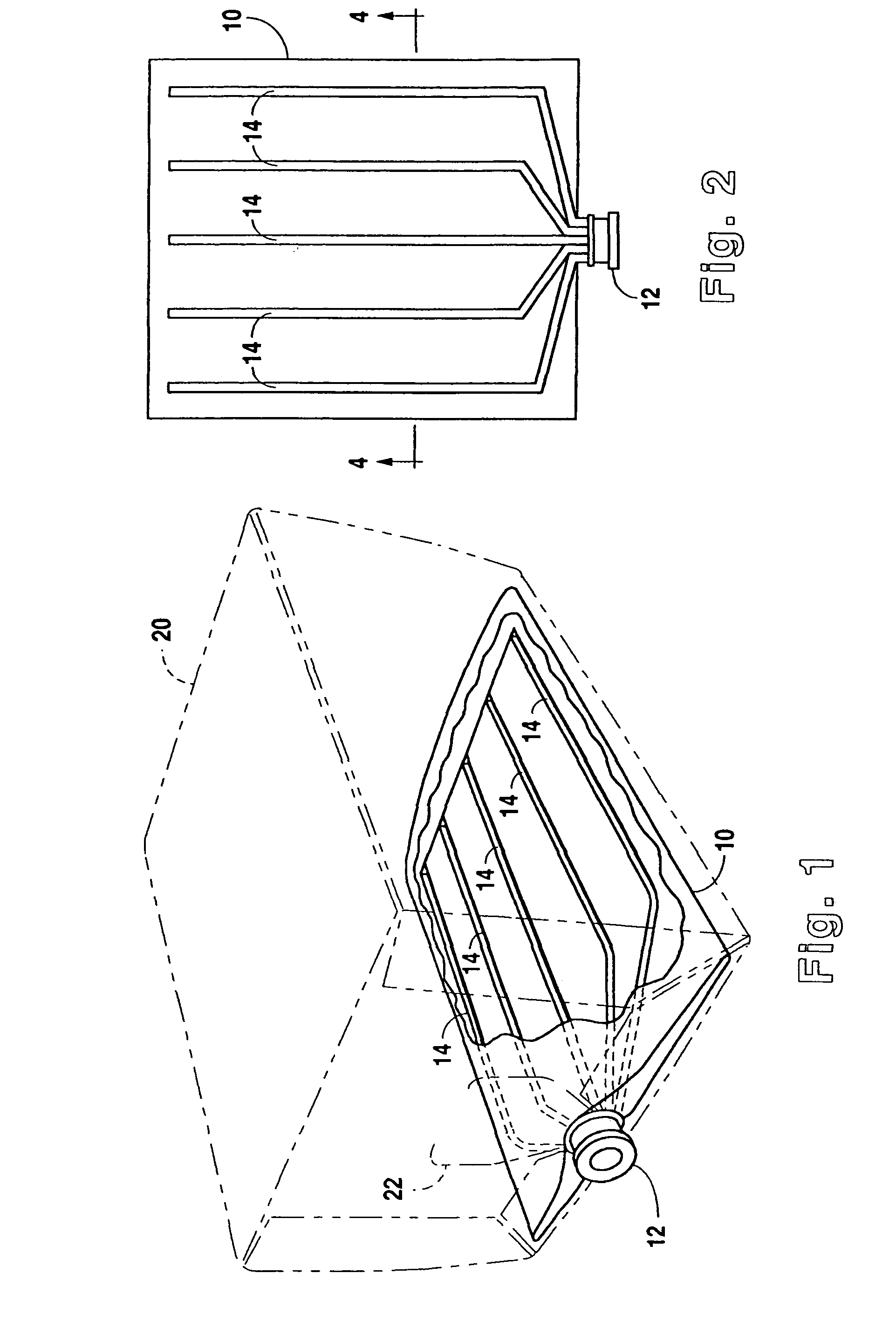
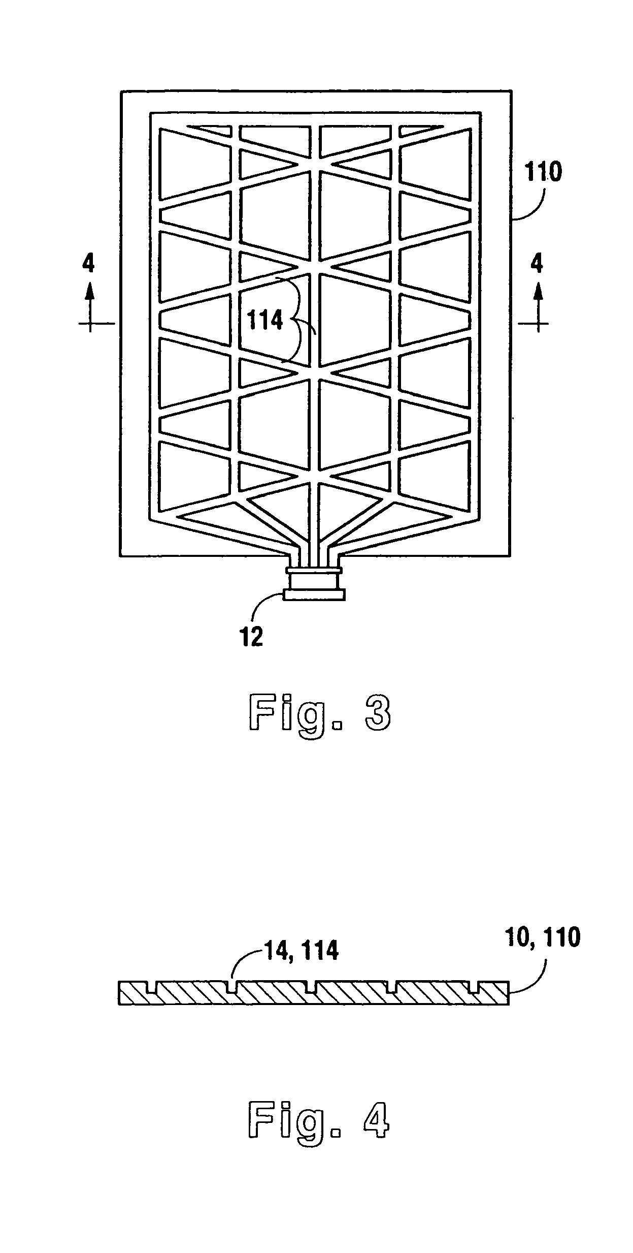
[0018]Referring to FIG. 1, a preferred embodiment of this invention comprises a collapsible bag 10 having a spout 12 and a plurality of grooves 14 on the interior of the bottom wall of bag 10. Bag 10, which is useful for containing and dispensing a liquid such as a beverage (not shown), is adaptable for insertion into a box 20 to form a bag-in-box apparatus. Spout 12 protrudes through a flap opening 22 of box 20. FIG. 2 more clearly illustrates the interior of the bottom wall of bag 10 with grooves 14, which are in liquid communication with spout 12. As liquid is dispensed from spout 12, bag 10 gradually collapses. However, grooves 14 prevent the walls of bag 10 from sealing off the liquid from spout 12, which enables substantially complete evacuation of the liquid from bag 10. Collapsible bag 10 may be made of a pair of sheets of flexible material, such as a thermoplastic, polynylon, metallized plastic, or other suitable material, joined at the peripheries by means known in the art...


PUM


Abstract

This invention is directed to an improved collapsible bag having a spout and one or more grooves on the interior surface of a wall of the bag. The grooves, which are integral to a wall of the bag rather than on a separate evacuation strip, are in liquid communication with the spout and are sized such that the opposing wall of the bag is not completely forced into the grooves under the suction of conventional pumps which are used to withdraw the liquid from the bag. Thus, the grooves enable substantially complete withdrawal of the liquid from the bag without the use of an evacuation strip. Additionally, the present invention may be used in any orientation and does not require a slanted rack. Although the primary intended application of the present invention is in bag-in-box packages for containing and dispensing beverages, this invention may also be used to advantage in other liquid dispensing applications.

Description

CROSS-REFERENCE TO RELATED APPLICATIONS[0001]This application is a continuation of U.S. patent application Ser. No. 10 / 257,351 filed, Apr. 1, 2003 now abandoned which is the national stage of PCT / US01 / 12203 filed Apr. 13, 2001, which claims priority from U.S. Provisional Application Ser. No. 60 / 196,838 filed on Apr. 13, 2000, the disclosures of which are incorporated herein by reference.BACKGROUND OF THE INVENTION[0002]1. Field of the Invention[0003]This invention relates generally to an apparatus for containing and dispensing liquid. More specifically, this invention is directed to a collapsible container for use in a bag-in-box apparatus.[0004]2. Description of the Related Art[0005]In the field of post-mix beverage systems, an apparatus commonly known as a bag-in-box package is used to store and dispense beverages such as soft drinks. Typically, such bag-in-box packages comprise a collapsible bag or bladder disposed within a cardboard box. The bag has a spout for filling the bag w...

Claims


Application Information

Patent Timeline
Patent Type & Authority Patents(United States)
IPC IPC(8): B65D35/56B65D35/08B65D35/16B65D35/00B65D37/00B65D77/06
CPCB65D77/062
Inventor PROVENZA, FRANK L.
Owner DR PEPPER SEVEN UP
Why Eureka
Try Eureka