Powered surgical stapling device

a stapling device and stapling technology, applied in the field of surgical staplers, can solve the problems of limited user control of the stapling process, device does not provide any tactile feedback, and surgeon's hand fatigu

Active Publication Date: 2008-09-09
TYCO HEALTHCARE GRP LP
View PDF28 Cites 1652 Cited by
  • Summary
  • Abstract
  • Description
  • Claims
  • Application Information

AI Technical Summary

Problems solved by technology

Current known devices can typically require 10-60 pounds of manual hand force to clamp tissue and deploy and form surgical fasteners in tissue which, over repeated use, can cause a surgeon's hand to become fatigued.
However, both of

Method used


Image

  • Powered surgical stapling device
  • Powered surgical stapling device
  • Powered surgical stapling device

Examples


Embodiment Construction

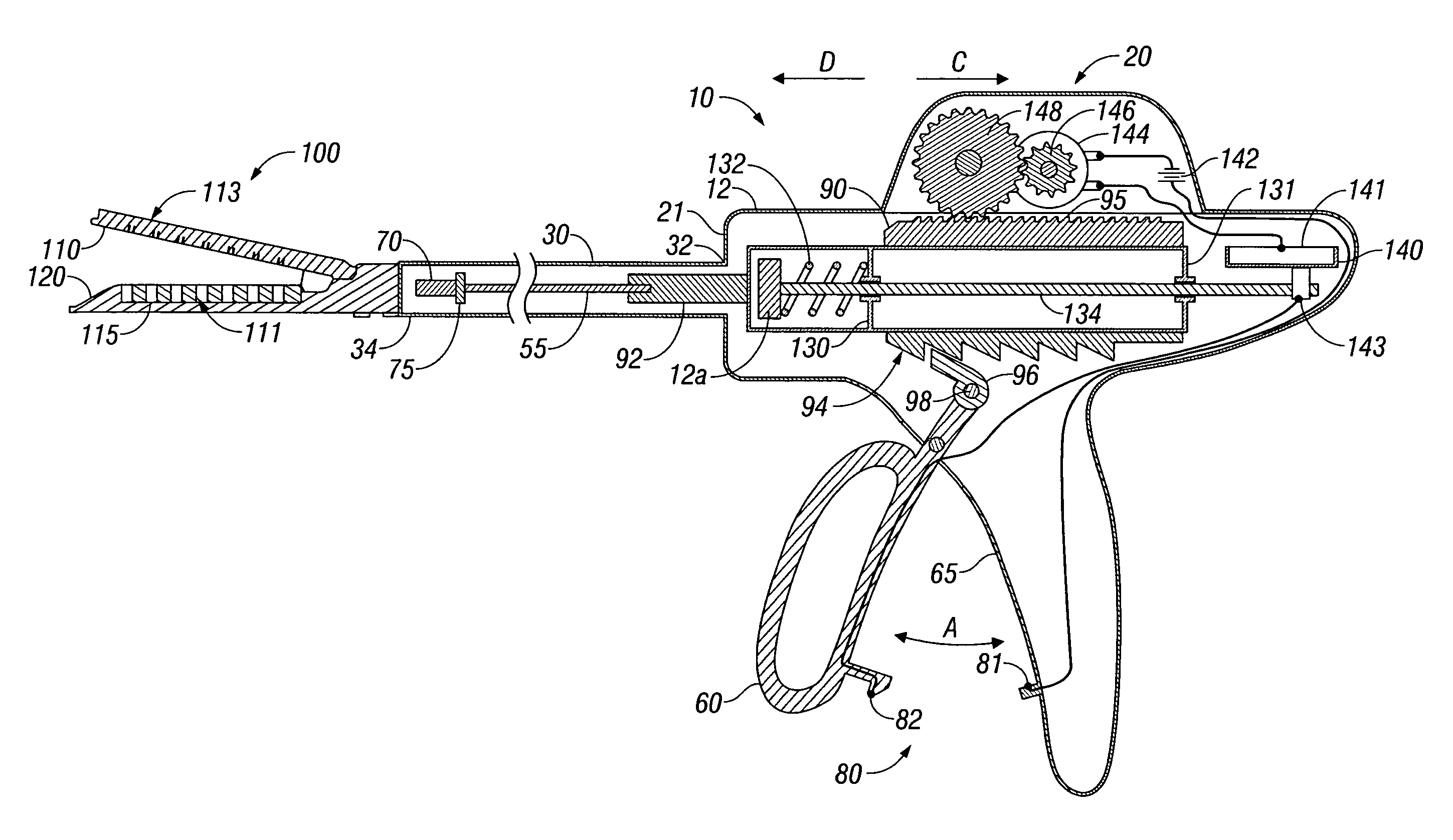
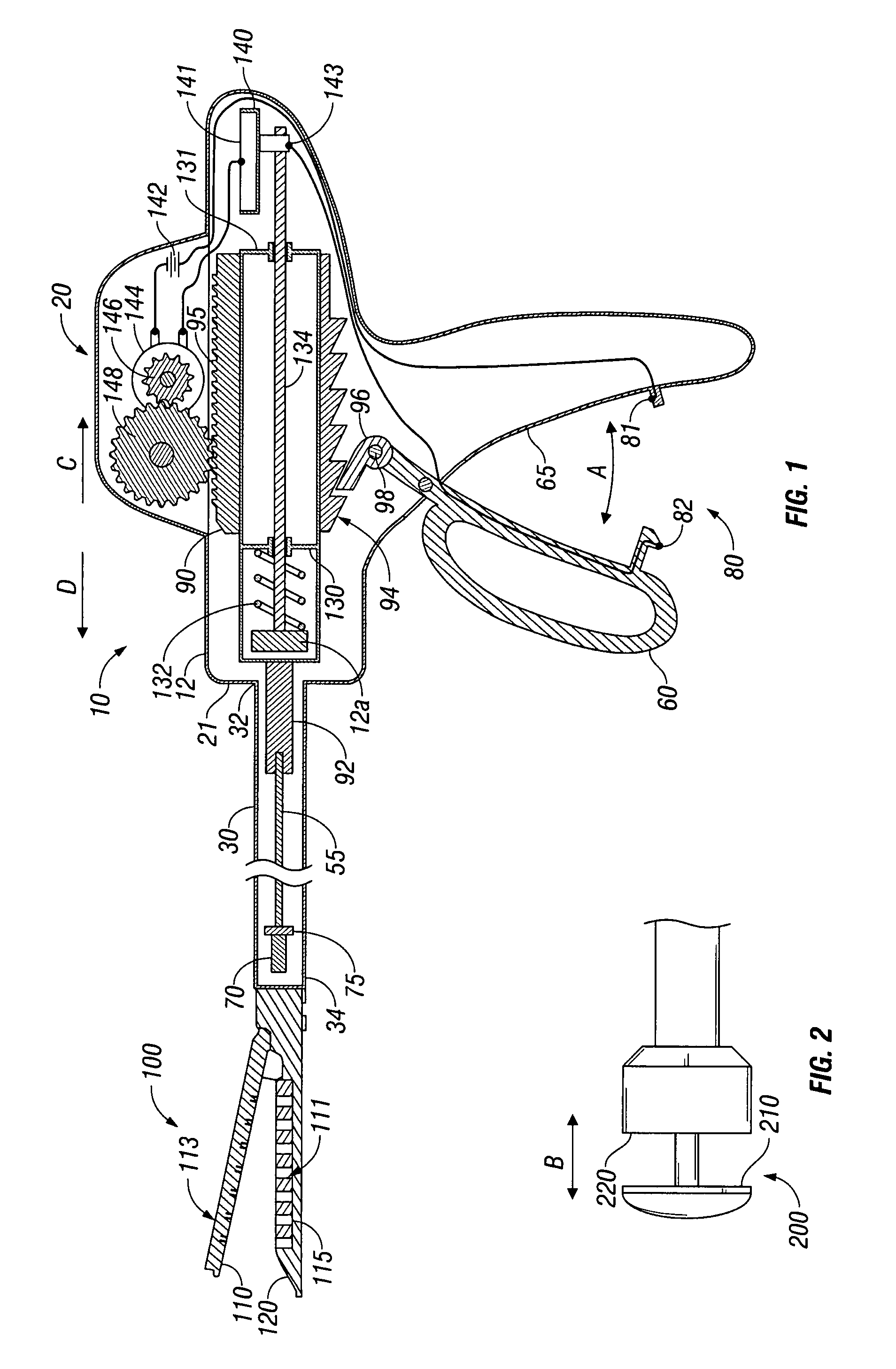
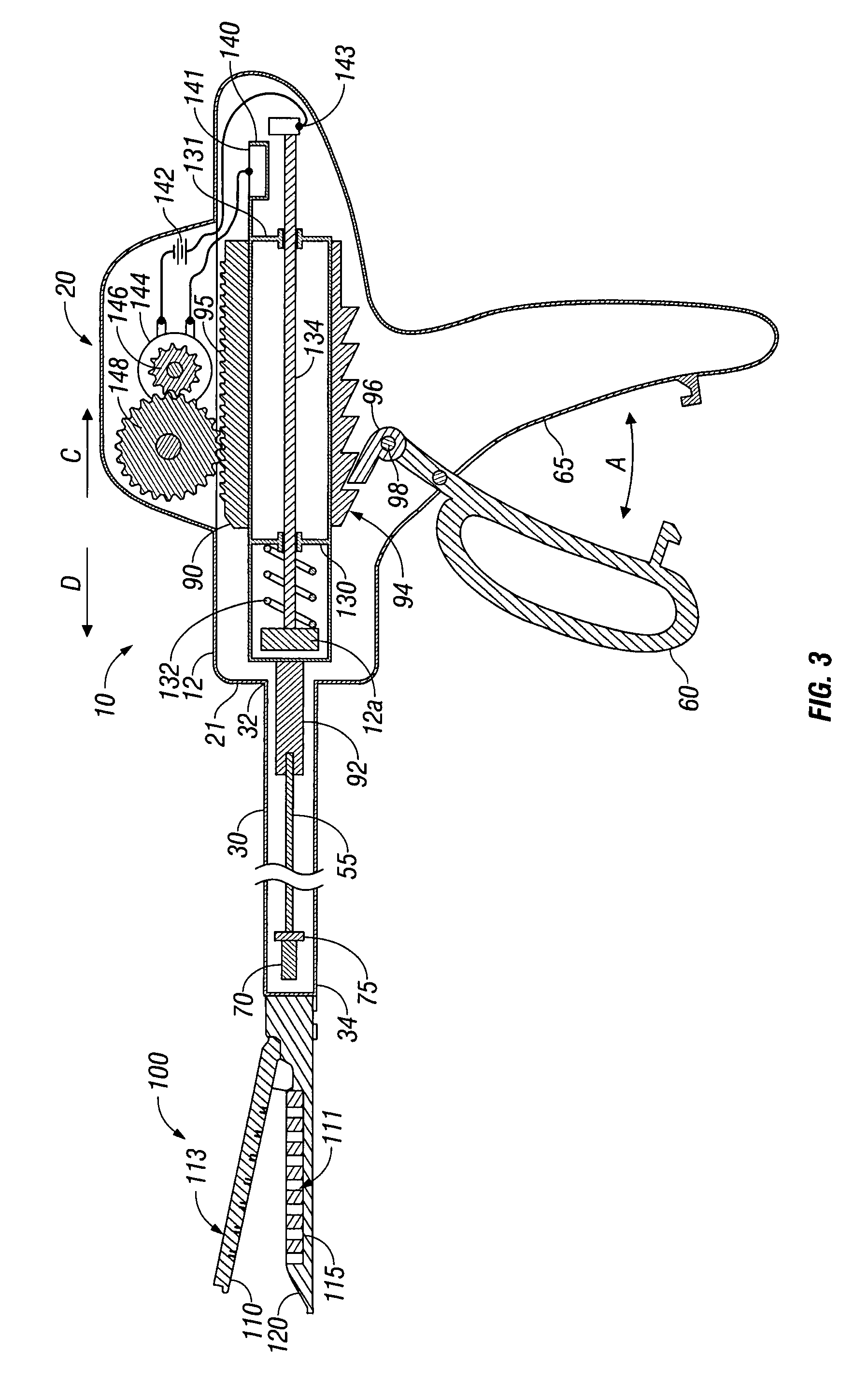
[0015]Referring initially to the embodiment disclosed in FIGS. 1 and 2, a surgical stapler 10 is shown having a motor-powered drive assembly here shown as including a drive assembly 20. It is envisioned that the presently disclosed drive assembly 20 can be utilized with any type of known surgical stapler. As such, a general surgical stapler 10 is schematically depicted in the drawings and described herein. For example, stapler 10 includes a housing 12 having an elongated member or shaft 30 attached thereto. Shaft 30 includes a proximal end 32 which attaches to a distal end 21 of the housing 12 and a distal end 34 which operatively couples to a tool assembly such as an end effector 100 or a tool assembly 200. The end effector 100 depicted in FIG. 1 is a conventional longitudinal stapler having opposing tissue contacting surfaces 110 and 120. The contact surface 110 acts as an anvil assembly 113 and the contact surface 120 includes a cartridge assembly 111 having a plurality of surgic...


PUM

PropertyMeasurementUnit
Forceaaaaaaaaaa
Electric potential / voltageaaaaaaaaaa

Abstract

A surgical stapler which includes a tool assembly having a pair of opposing tissue engaging surfaces for deforming a plurality of surgical fasteners through and fastening tissue is disclosed. The surgical stapler includes a housing having a fixed handle and a movable handle mounted to the housing and selectively movable relative to the fixed handle from a first position to a second position to actuate the clamping of tissue. The stapler further includes a drive assembly including a motor, a power source and a coupling member. The motor engages the coupling member, wherein movement of the movable handle to the second position activates the motor, which advances a firing shaft and forces a firing piston into the tool assembly to deform the surgical fasteners through and fasten tissue.

Description

BACKGROUND[0001]1. Technical Field[0002]The present disclosure relates to a surgical stapler for implanting mechanical surgical fasteners into the tissue of a patient, and, in particular, to a surgical stapler which is powered by a motor for firing surgical fasteners into tissue.[0003]2. Background of Related Art[0004]Current known devices can typically require 10-60 pounds of manual hand force to clamp tissue and deploy and form surgical fasteners in tissue which, over repeated use, can cause a surgeon's hand to become fatigued.[0005]Gas powered pneumatic staplers which implant surgical fasteners into tissue are known in the art. Certain of these instruments utilize a pressurized gas supply which connects to a trigger mechanism by way of an intricate series of hoses and actuators. The trigger mechanism, when depressed, simply releases pressurized gas to implant a fastener into tissue.[0006]Motor-powered surgical staplers are also known and are disclosed in U.S. Pat. No. 5,383,880 t...

Claims


Application Information

Patent Timeline
IPC IPC(8): A61B17/068
CPCA61B17/07207A61B17/068A61B17/115A61B2017/00181A61B2017/00734A61B2017/2923A61B2017/00398A61B17/072A61B2017/00022
Inventor MARCZYK, STANISLAW
Owner TYCO HEALTHCARE GRP LP
Why Eureka
Try Eureka