Adaptive radio transceiver with a local oscillator

a radio transceiver and local oscillator technology, applied in the field of telecommunication systems, can solve the problems of difficult integration of the transceiver into a single ic, many applications are not fully commercialized, etc., and achieve the effects of high data rate wireless, high cost, size and power consumption

Inactive Publication Date: 2006-04-18
AVAGO TECH INT SALES PTE LTD
View PDF22 Cites 68 Cited by
  • Summary
  • Abstract
  • Description
  • Claims
  • Application Information

AI Technical Summary

Benefits of technology

[0004]Transceivers have a wide variety of applications ranging from low data rate wireless applications (such as mouse and keyboard) to medium data rate Bluetooth and high data rate wireless LAN 802.11 standards. However, due to the high cost, size and power consumption of currently available transceivers, numerous applications are not being fully commercialized. A simplified architecture would make a transceiver more economically viable for wider applications and integration with other systems. The integration of the transceiver into a single integrated circuit (IC) would be an attractive approach. However, heretofore, the integration of the transceiver into a single IC has been difficult due to process variations and mismatches. Accordingly, there is a need for an innovative transceiver architecture that could be implemented on a single IC, or alternatively, with a minimum number of discrete off-chip components that compensate for process variations and mismatches.

Problems solved by technology

However, due to the high cost, size and power consumption of currently available transceivers, numerous applications are not being fully commercialized.
However, heretofore, the integration of the transceiver into a single IC has been difficult due to process variations and mismatches.

Method used


Image

  • Adaptive radio transceiver with a local oscillator
  • Adaptive radio transceiver with a local oscillator
  • Adaptive radio transceiver with a local oscillator

Examples


Embodiment Construction

Exemplary Embodiments of a Transceiver

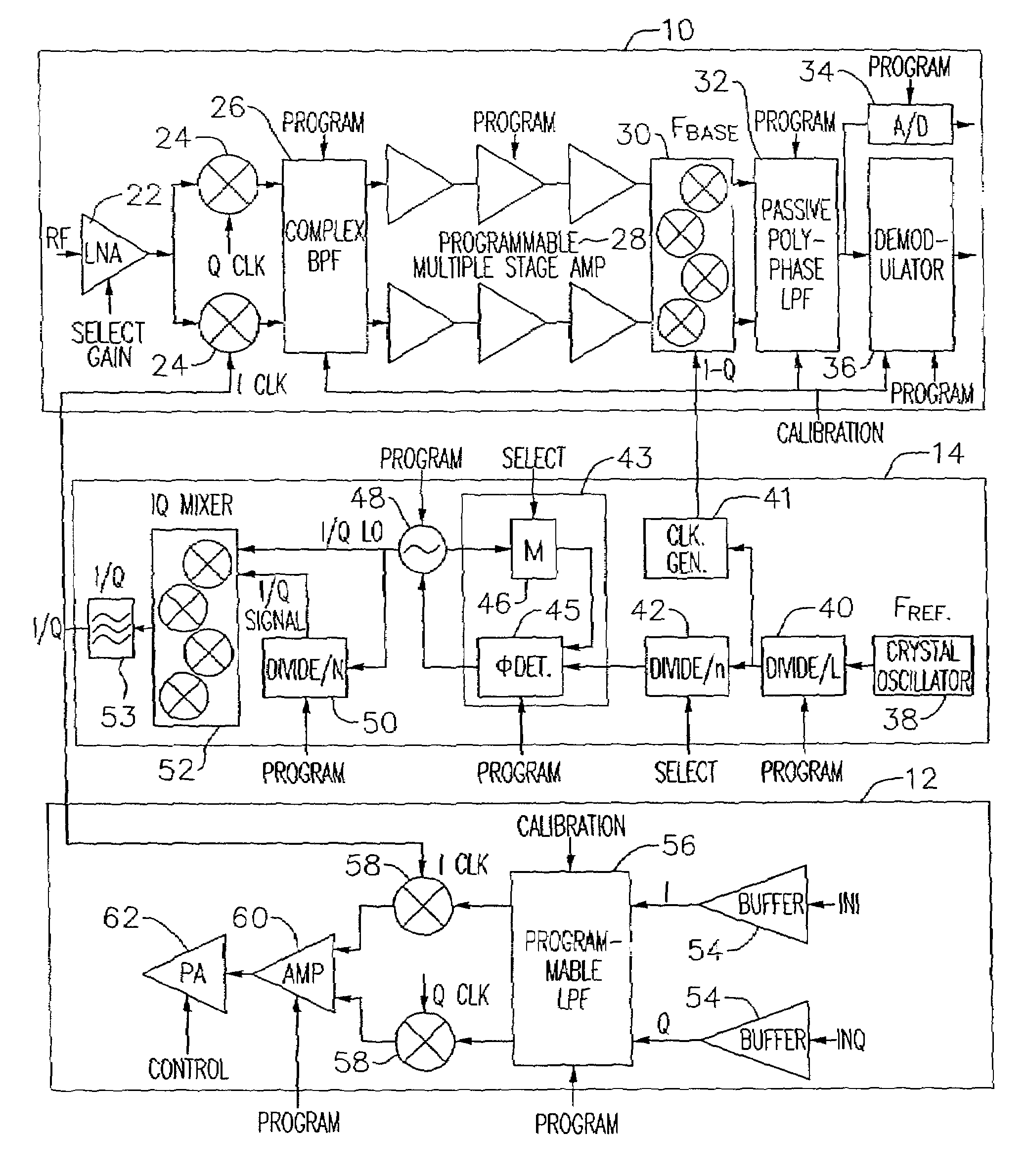
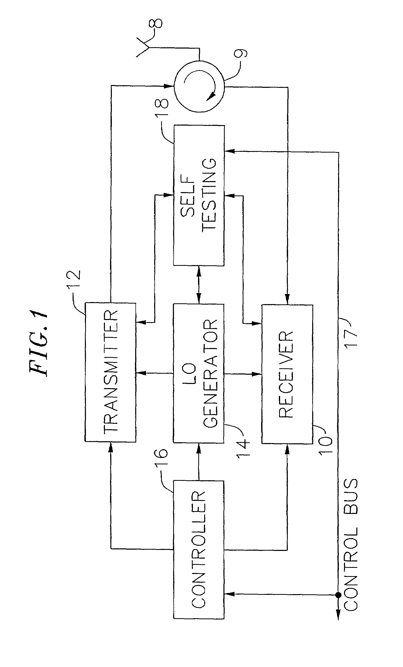
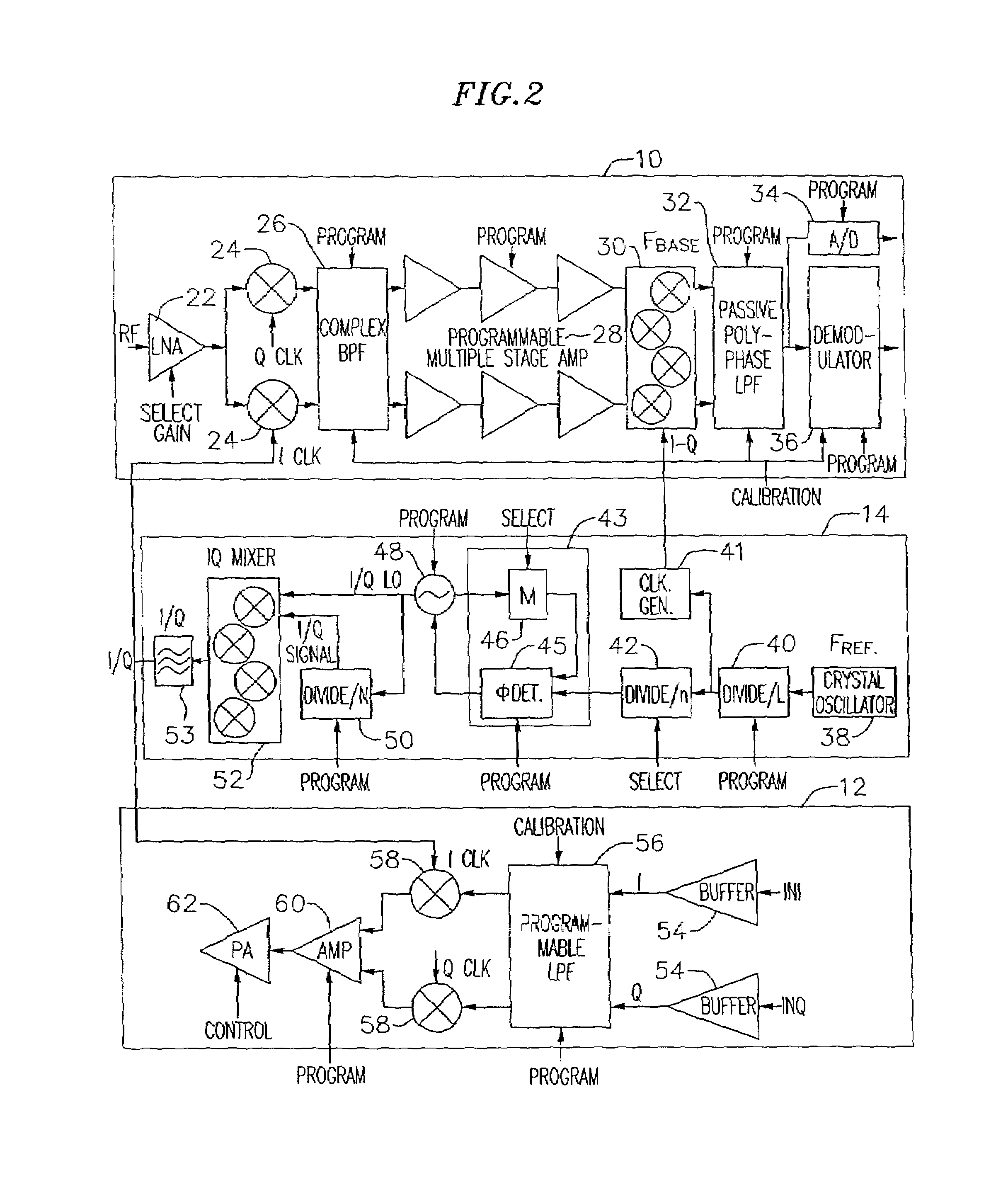
[0074]In accordance with an exemplary embodiment of the present invention, a transceiver utilizes a combination of frequency planning, circuit design, layout and implementation, differential signal paths, dynamic calibration, and self-tuning to achieve robust performance over process variation and interference. This approach allows for the full integration of the transceiver onto a single IC for a low cost, low power, reliable and more compact solution. This can be achieved by (1) moving external bulky and expensive image reject filters, channel select filters, and baluns onto the RF chip; (2) reducing the number of off-chip passive elements such as capacitors, inductors, and resistors by moving them onto the chip; and (3) integrating all the remaining components onto the chip. As those skilled in the art will appreciate, the described exemplary embodiments of the transceiver do not require integration into a single IC and may be implemented in ...


PUM


Abstract

An exemplary embodiment of the present invention described and shown in the specification and drawings is a transceiver with a receiver, a transmitter, a local oscillator (LO) generator, a controller, and a self-testing unit. All of these components can be packaged for integration into a single IC including components such as filters and inductors. The controller for adaptive programming and calibration of the receiver, transmitter and LO generator. The self-testing unit generates is used to determine the gain, frequency characteristics, selectivity, noise floor, and distortion behavior of the receiver, transmitter and LO generator. It is emphasized that this abstract is provided to comply with the rules requiring an abstract which will allow a searcher or other reader to quickly ascertain the subject matter of the technical disclosure. It is submitted with the understanding that it will not be used to interpret or limit the scope or the meaning of the claims.

Description

CROSS-REFERENCE TO RELATED APPLICATION[0001]The present application is a continuation of patent application Ser. No. 09 / 691,633, filed Oct. 18, 2000, now issued U.S. Pat. No. 6,404,293 B1, which is a continuation of patent application Ser. No. 09 / 634,552, filed Aug. 8, 2000, which claims priority to and benefit from provisional Application No. 60 / 160,806, filed Oct. 21, 1999; Application No. 60 / 163,487, filed Nov. 4, 1999; Application 60 / 163,398, filed Nov. 4, 1999; Application No. 60 / 164,442, filed Nov. 9, 1999, Application No. 60 / 164,494, filed Nov. 9, 1999; Application No. 60 / 164,314, filed Nov. 9, 1999; Application No. 60 / 165,234, filed Nov. 11, 1999; Application No. 60 / 165,239, filed Nov. 11, 1999; Application No. 60 / 165,356, filed Nov. 12, 1999; Application No. 60 / 165,355, filed Nov. 12, 1999; Application No. 60 / 172,348, filed Dec. 16, 1999; Application No. 60 / 201,335, filed May 2, 2000; Application No. 60 / 201,157, filed May 2, 2000; Application No. 60 / 201,179, filed May 2, 20...

Claims


Application Information

Patent Timeline
Patent Type & Authority Patents(United States)
IPC IPC(8): H04B1/40H03H11/12H03H21/00
CPCH03B21/01H03H11/1291H03H21/0001H03H21/0012H04B17/19H04B1/30H04B1/40H04B17/104H04B17/14H03H2011/0494H03J2200/10H03B27/00
Inventor DARABI, HOOMANROFOUGARAN, AHMADREZAROFOUGARAN, MARYAM
Owner AVAGO TECH INT SALES PTE LTD
Why Eureka
Try Eureka