
Pin pallet

a pallet and pin technology, applied in the field of pallets, can solve the problems of occupying valuable storage spa

Active Publication Date: 2006-05-16
MILLER DONALD R
View PDF19 Cites 88 Cited by
  • Summary
  • Abstract
  • Description
  • Claims
  • Application Information

AI Technical Summary

Benefits of technology

[0007]Another object of the present invention, which shall become apparent as the detailed description proceeds, is achieved by a pallet comprising a frame; at least one rail secured to the frame, the at least one rail having a rail slot; and a pin mechanism slidably received in the slot, the pin mechanism having a pin that is moveable between a first and a second position.
[0008]A pin pallet comprising a frame; at least one rail secured to the frame, the at least one rail having a slot; and a pin mechanism slidably received in the slot, the pin mechanism having a pallet pin moveable along the entire length of the slot, wherein the pin mechanism includes a cam mechanism for selectively clamping and unclamping the pin mechanism to the at least one slot.
[0009]A pin pallet for holding metal stampings during transfer comprising a frame; at least one rail secured to the frame, the at least one rail having a slot; a pin mechanism slidably received in the slot including a locking plate received within the interior of the at least one rail, a slide plate positioned on the exterior of the at least one rail, and adapted to slide within the slot, the locking plate and the side plate having apertures therethrough, a mounting stub extending through the apertures and coupled to the locking plate, a pin collar provided at one end of the pallet pin, the pin collar having a pin collar bore adapted to receive the mounting stub, a handle assembly including a handle and a handle collar having a handle collar bore adapted to receive the mounting stub, a spring carried by the mounting stub, and interposed between the pin collar and the slide plate, and a cam mechanism incorporating the mounting stub and the handle assembly, the cam mechanism having a camming pin secured to the mounting stub, and a curvilinear cam slot disposed on the handle collar, wherein the camming pin and the curvilinear cam slot interact when the handle assembly is actuated to selectively lock and unlock the cam mechanism.

Problems solved by technology

A further drawback of the current pin pallet configuration is that when the pallets are not in use they take up valuable storage space in view of their size and profile.

Method used


Image

  • Pin pallet
  • Pin pallet
  • Pin pallet

Examples


Embodiment Construction

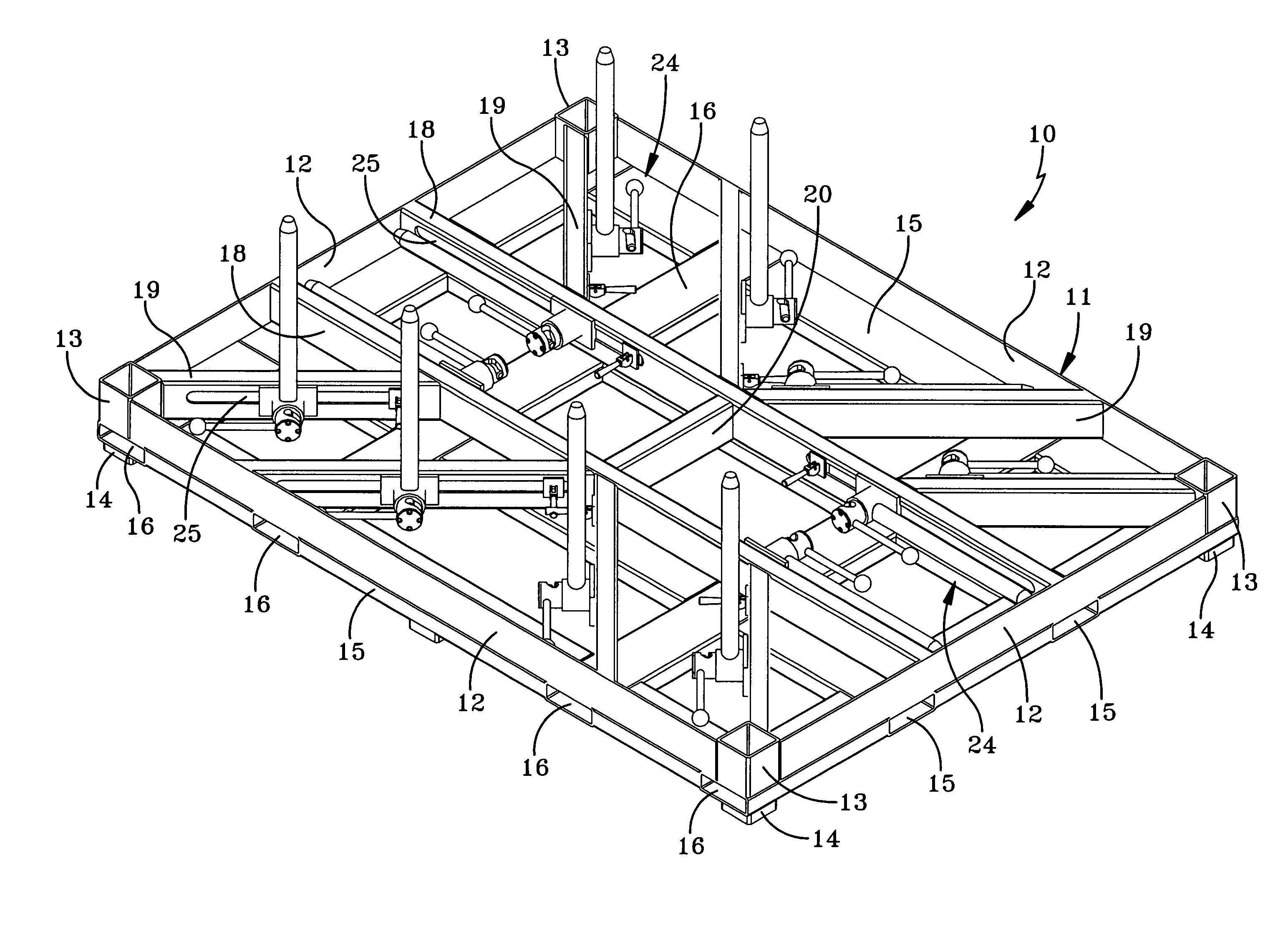
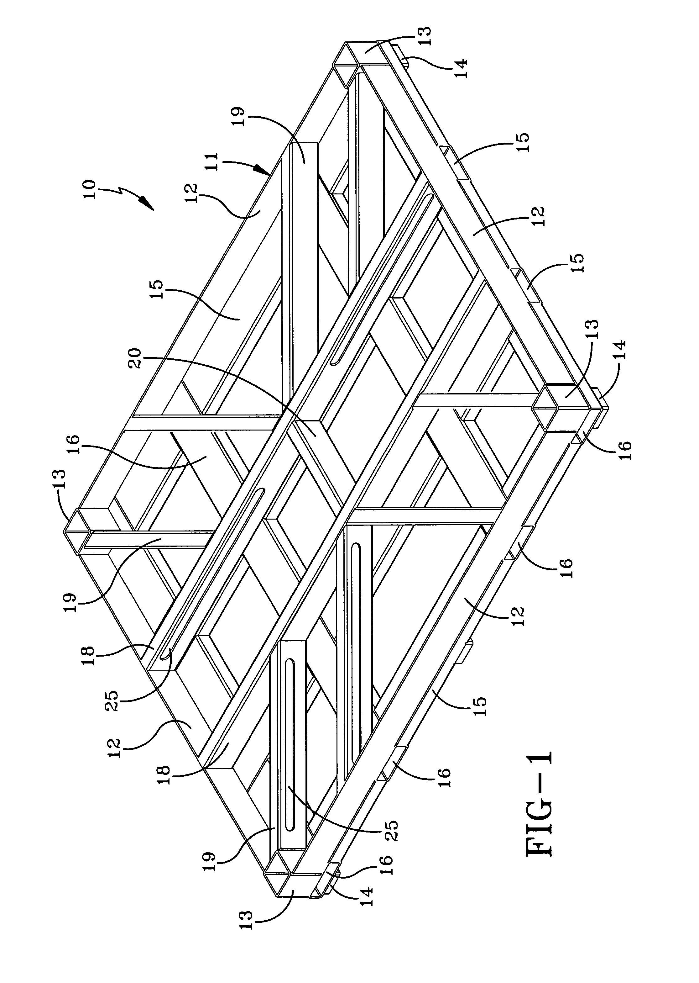
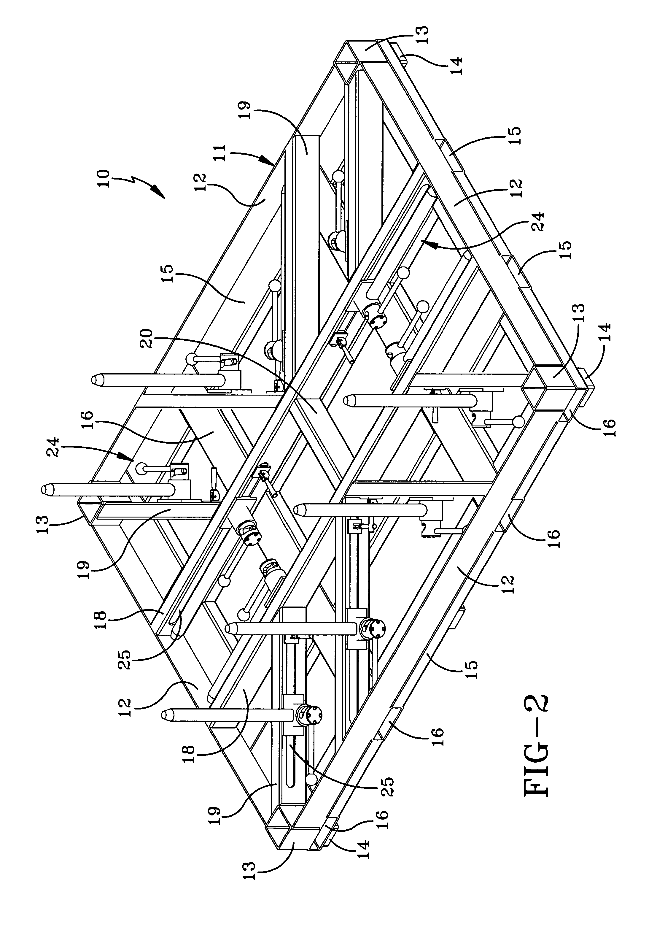
[0023]Referring now to the drawings and in particular to FIGS. 1–3, it can be seen that a pallet according to the present invention is designated generally by the numeral 10. The pallet 10 includes a frame 11 which has a plurality of side members 12. As shown in the drawings, the side members 12 are arranged in a rectangular configuration. Positioned at each of the four corners of the frame 11 are four junction members 13. Each junction member 13 is substantially hollow, and joins adjacent side members 12 together. Altering the shape of the four junction members 13, and altering the length of the side members 12 will effect the shape of the frame 11. Therefore, it will be appreciated that the frame 11 could have a square configuration, or other shape deemed appropriate for the required application.

[0024]Extending downwardly from each junction member 13 are leg members 14. The leg members 14 have the same shape as the junction members 13, but are adapted to have smaller dimensions. T...


PUM


Abstract

A pallet includes a frame and at least one rail secured to the frame. The rail has a slot which slidably receives a pin mechanism. The pin mechanism includes a pallet pin that is moveable along the entire length of the slot, wherein the pallet pin is moveable between a position flush with the frame to a position substantially perpendicular with respect to the frame.

Description

CROSS-REFERENCE TO RELATED APPLICATION[0001]This application claims the benefit of U.S. Provisional Application No. 60 / 395,237 filed on Jul. 11, 2002.TECHNICAL FIELD[0002]The present invention is generally directed to pallets and more particularly to pallets with pin mechanisms that are slidable and pivotable.BACKGROUND ART[0003]Current pin pallets are configured with a frame and a plurality of perpendicularly extending pins. These pins are permanently welded into place for the purpose of holding shaped blank metal sheets that are to be stamped. The pallet is used to move the metal blanks from a storage location, or manufacturing station, to another location. The pins are positioned on the pallets so as to precisely position the metal blanks to allow for stamping equipment or robots to easily select one metal sheet for placement in a stamping machine. Accordingly, for different shaped metal blanks, a unique pin pallet is required with appropriately positioned pins to keep the metal ...

Claims


Application Information

Patent Timeline
Patent Type & Authority Patents(United States)
IPC IPC(8): B65D19/44
CPCB65D19/44
Inventor MILLER, DONALD R.
Owner MILLER DONALD R
Features
  • Generate Ideas
  • Intellectual Property
  • Life Sciences
  • Materials
  • Tech Scout
  • Unparalleled Data Quality
  • Higher Quality Content
  • 60% Fewer Hallucinations
Learn More