Projection display having an illumination module and an optical modulator

a projection display and optical modulator technology, applied in the field of projection displays, can solve the problems of limiting the downsizing of illumination modules, the need for replacement of lamps, and the large size of illumination modules, and achieve the effect of small projection displays and longer life span

Inactive Publication Date: 2006-06-27
SAMSUNG ELECTRONICS CO LTD
View PDF17 Cites 12 Cited by
  • Summary
  • Abstract
  • Description
  • Claims
  • Application Information

AI Technical Summary

Benefits of technology

[0013]The present invention provides a projection display employing an improved illumination module which includes a plurality of light emitting devices and a light guide panel to realize a smaller projection display and achieve a longer life span.

Problems solved by technology

Therefore, when the conventional projection display is used a lot, it has a drawback in that the lamp should be replaced often.
The conventional projection display has another drawback in that a plurality of mirrors and lenses are used and accordingly an illumination module is quite large.
Thus, there is a limit to downsizing the illumination module.

Method used


Image

  • Projection display having an illumination module and an optical modulator
  • Projection display having an illumination module and an optical modulator
  • Projection display having an illumination module and an optical modulator

Examples


Embodiment Construction

[0039]The present invention will now be described more fully with reference to the accompanying drawings, in which exemplary embodiments of the invention are shown.

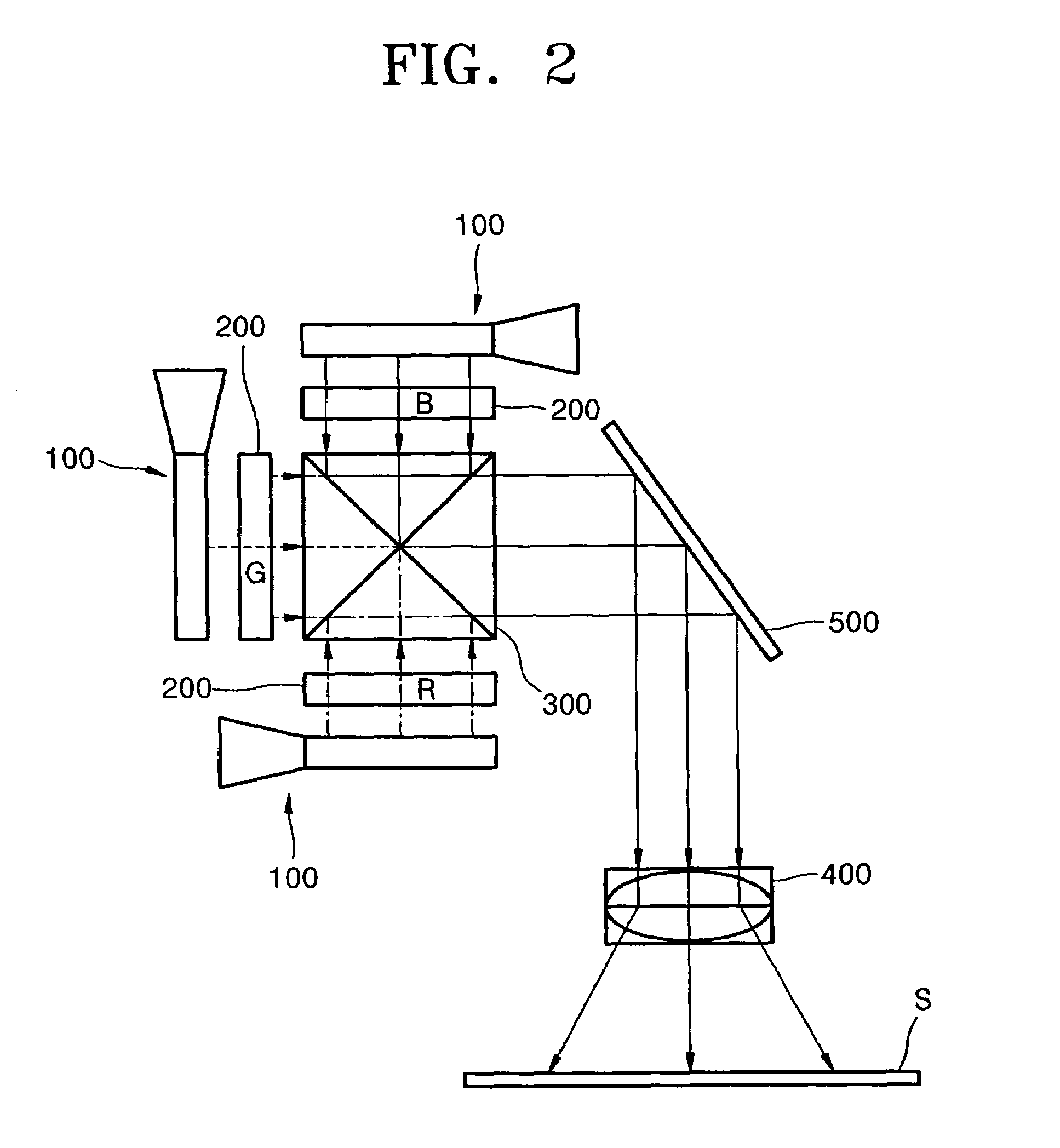
[0040]FIG. 2 is a schematic diagram illustrating the configuration of a projection display according to an exemplary embodiment of the present invention.

[0041]Referring to FIG. 2, a projection display according to the present embodiment includes liquid crystal panels 200R, 200G, and 200B, three illumination modules 100 for illuminating the liquid crystal panels 200R, 200G, and 200B, a synthesis prism 300 for synthesizing three colored light beams which are respectively modulated by liquid crystal panels 200R, 200G and 200B, and a projection optical system 400 for projecting synthesized light on an enlarged scale onto a screen S. Reference numeral 500 is a reflecting mirror which guides light which has passed through the synthesis prism 300 to the projection optical system 400.

[0042]The liquid crystal panel 200 is a projec...


PUM

PropertyMeasurementUnit
refractive indexaaaaaaaaaa
azimuth angle A1aaaaaaaaaa
critical angleaaaaaaaaaa

Abstract

Provided is a projection display including an illumination module. The illumination module includes a light source including a plurality of light emitting devices, a light guide panel having a top surface from which light is emitted, the top surface facing the optical modulator, and an edge surface on which light is incident, and an optical transport member for guiding light emitted from the light source to the edge surface of the light guide panel, the section of the optical transport member parallel to the edge surface increasing in size from the edge surface to the light source.

Description

BACKGROUND OF THE INVENTION[0001]This application claims the priority of Korean Patent Application No. 2003-23726, filed on Apr. 15, 2003, in the Korean Intellectual Property Office, the disclosure of which is incorporated herein in its entirety by reference.[0002]1. Field of the Invention[0003]The present invention relates to a projection display that projects an enlarged image onto a screen.[0004]2. Description of the Related Art[0005]In recent years, projection displays that project an enlarged image, which has been modulated by an optical modulator such as a liquid crystal panel, onto a screen have become popular.[0006]FIG. 1 is a schematic diagram illustrating the configuration of a conventional projection display.[0007]Referring to FIG. 1, a conventional projection display comprises a liquid crystal panel 20 which is an optical modulator, an illumination module 10 for emitting light to the liquid crystal panel 20, and a projection lens 40 for projecting a modulated image on an...

Claims


Application Information

Patent Timeline
Patent Type & Authority Patents(United States)
IPC IPC(8): G03B21/14G02F1/1335G02B27/09G02B27/18G03B21/00G03B21/20G03B21/28
CPCG02B27/0994H04N9/3152G02B19/0028G03B21/208G02B19/0066G03B21/2033G03B21/14
Inventor LEE, YOUNG-CHOLKURATOMI, YASUNORI
Owner SAMSUNG ELECTRONICS CO LTD
Why Eureka
Try Eureka