Color filter substrate, liquid crystal display device, electronic apparatus, and methods for manufacturing color filter substrate and liquid crystal display device

a technology of color filter substrate and liquid crystal display device, which is applied in the direction of printing, optics, instruments, etc., can solve the problems of high consumption of coloring inks, high wastage of materials used in forming colored layers, and frequency increase of coloring inks discharge onto coloring parts that correspond to pixels, etc., to reduce the wastage of color element forming material, and the effect of reducing the area siz

Inactive Publication Date: 2007-06-21
SEIKO EPSON CORP
View PDF10 Cites 7 Cited by
  • Summary
  • Abstract
  • Description
  • Claims
  • Application Information

AI Technical Summary

Benefits of technology

[0011] An advantage of the invention is to provide a color filter substrate, a liquid crystal display device and electronic apparatus, as well as methods for manufacturing the color filter substrate and the liquid crystal display device, where the color filter substrate is provided with color elements having a uniform quality in the color element regions, while allowing to reduce the wastage of the color element forming material.
[0012] According to a first aspect of the invention, a color filter substrate includes: a first partition wall for partitioning a substrate into a plurality of color element regions; a second partition wall for dividing each of the plurality of color element regions into a plurality of regions; color elements having a plurality of types, being formed on the plurality of color element regions; a transparent electrode covering the first partition wall, the second partition wall, and the color element; and a projection or an aperture formed on the transparent electrode; wherein the second partition wall is arranged in the direction in which the projection or the aperture is extended.
[0013] In the above color filter substrate, the second partition wall is formed so as to divide the color element regions partitioned by the first partition wall into a plurality of regions. Therefore, compared to the case without the second partition wall, it is easier to flatten the color elements being formed, since those color elements are formed per plurality of regions, each having smaller area size as a result of dividing the color element regions. The second partition wall has little affect on display, particularly in the color filter substrates used for a large-sized liquid crystal display device, even in the case of dividing the color element region into the plurality of regions with the second partition wall, since the size of the color element region corresponding to a display pixel is large. Moreover, the second partition wall is arranged in the direction, in which the projection or the aperture, formed on the transparent electrode is extended. As a result, the color elements are not arranged under the projections or apertures that do not contribute to the display, in contrast to the case where the projections or apertures for orientation control are formed on the transparent electrode covering the color elements. That is to say, it is possible to reduce the wastage of the color element forming material, and the color filter substrate having the color elements with a uniform quality are provided in the color element regions.
[0014] It is desirable that those color elements be formed by discharging functional fluids containing color element forming materials, to the color element regions. Here, the color element regions are partitioned by the first partition wall, and they are further divided into the plurality of regions by the second partition wall. This allows the color elements to have uniform film thickness and flatness, since the functional fluid containing the color element forming material is discharged and pervaded to the color element regions per plurality of regions, each of which having a smaller area after being divided. That is to say, it is possible reduce clear defects, in which the color elements are not formed in some part of the color element regions, providing the color filter substrate having the color elements with a uniform quality in the color element regions.
[0015] It is desirable that the above-referenced color elements to have an approximately the same film thickness as that of the first partition wall and the second partition wall. When an orientation film is formed covering the substrate surface, so as to orient the liquid crystals in an approximately vertical direction, the above structure allows the color element regions to be divided into the plurality of orientation-controlled regions having the second partition wall as a boarder, without causing irregularity in liquid crystal orientation at the boundary between the color element and the first partition wall or the second partition wall.
[0016] According to a second aspect of the invention, a liquid crystal display device includes, the color filter substrate according the first aspect of the invention; a counter substrate having a plurality of pixel electrodes corresponding to the plurality of color element regions on the color filter substrate; and liquid crystals sandwiched by the color filter substrate and the counter substrate; wherein an orientation film is provided to surfaces which contact the liquid crystals, the orientation film orienting molecules of liquid crystals in a direction approximately vertical to the surfaces of the color filter substrate and of the counter substrate.

Problems solved by technology

In recent years, liquid crystal display devices in MVA mode are employed for colored televisions, and the sizes of those screens are increasingly getting larger This causes the size increase of the color filter substrate being used, resulting in a problem of requiring many complex processing steps, such as substrate coating with photosensitive resin, exposure, development and washing, as well as extensive equipments compliant with larger-sized substrates, in order to form, using photolithography, the colored layers or projections for orientation control.
Moreover, in the color filters mentioned above, projections for controlling orientation are formed on the deposited colored layers, resulting in a problem that the materials used in forming the colored layers are consumed in a high wastage, since the colored layer under the projections are not effective for actual display.
However, in this technique, a phenomenon called “clear defect” occurs, since it is difficult to pervade coloring inks throughout the corners of pixels, as the pixel size increases in the liquid crystal display device, causing the frequency increase of the coloring inks discharge onto the coloring parts that correspond to the pixels.
The above inkjet method also involves a problem that it is difficult to assure the flatness of the surface of the colored layers.

Method used


Image

  • Color filter substrate, liquid crystal display device, electronic apparatus, and methods for manufacturing color filter substrate and liquid crystal display device
  • Color filter substrate, liquid crystal display device, electronic apparatus, and methods for manufacturing color filter substrate and liquid crystal display device
  • Color filter substrate, liquid crystal display device, electronic apparatus, and methods for manufacturing color filter substrate and liquid crystal display device

Examples


first embodiment

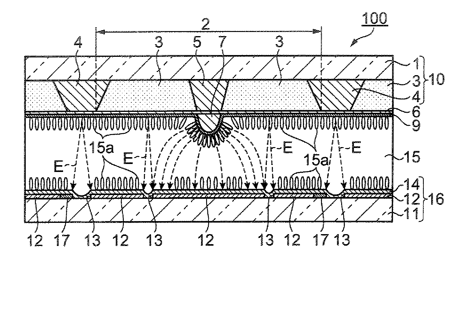
[0052] Color Filter Substrate

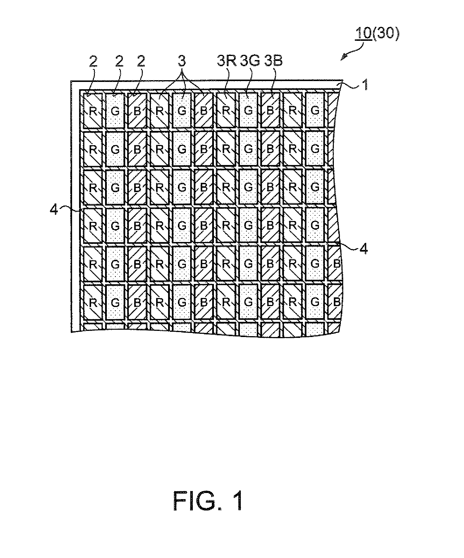
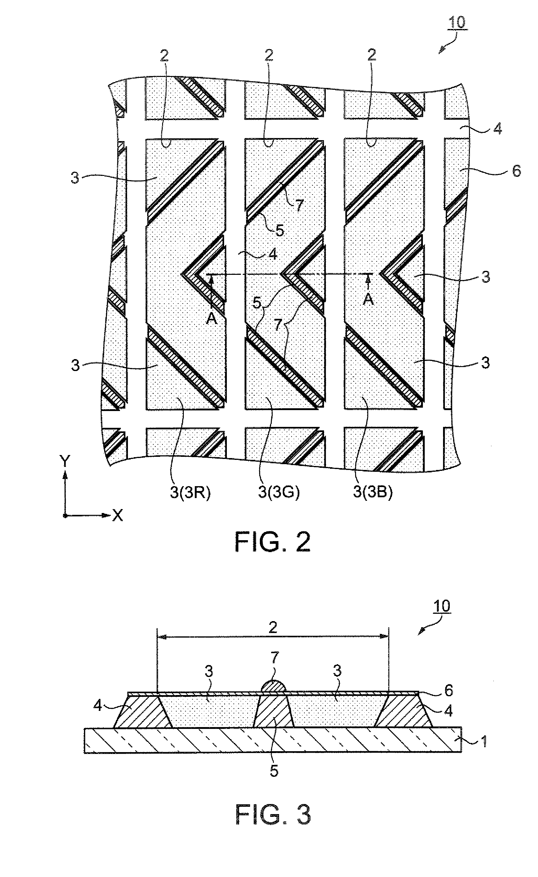
[0053]FIG. 1 is a schematic top view drawing showing a structure of a color filter substrate according to a first embodiment. As shown in FIG. 1, a color filter substrate 10 according to the first embodiment includes first partition walls 4 for partitioning a transparent glass substrate 1 (i.e. a substrate) into the plurality of color elements regions 2. Color elements 3 having three colors of red, green and blue (RGB) are formed in each of the color element regions 2. Color elements 3R, 3G, and 3B are arranged, so that color elements of the same color are arranged linearly In other words, the color filter substrate 10 has color elements 3 aligned in stripes.

[0054]FIG. 2 is a magnified top view drawing showing color element regions. As shown in FIG. 2, second partition walls 5 subdivide the color element regions 2 that are partitioned by the first partition walls 4 into a plurality of regions. The second partition walls 5 have a bent shape, extending a...

second embodiment

[0084] Color Filter Substrate

[0085] A color filter substrate according to a second embodiment will now be described. As shown in FIG. 1, a color filter substrate 30 according to the second embodiment includes, similar to the color filter substrate 10 according to the first embodiment, the first partition walls 4 for partitioning the transparent glass substrate I into the plurality of color elements regions 2, and the color elements 3R, 3G, and 3SB, formed on the plurality of color element regions 2, each representing different colors. Moreover, the color elements 3 are aligned in stripes, so that the color elements of the same color are arranged linearly. Hence, in the description hereafter, the same signs and numerals as that of the first embodiment are used for the parts that are common between the first and the second embodiment.

[0086]FIG. 8 is a magnified top view drawing, showing the color element regions of the color filter substrate according to the second embodiment. As sh...

third embodiment

[0121] Electronic Apparatus

[0122] A large-sized liquid crystal television as the electronic apparatus according to the third embodiment will now be described. FIG. 14 is a schematic oblique drawing showing a large-sized liquid crystal television. As shown in FIG. 14, a display unit 201 of a large-sized liquid crystal television 200 is mounted with either the liquid crystal display device 100 according to the first embodiment, or the liquid crystal display device 110 according to the second embodiment, both having a wide viewing angle.

[0123] The effects of the third embodiment are as follows.

[0124] The liquid crystal display devices 100 and 110 are manufactured in a high yield, with reduced defects such as clear defects and color irregularity. Hence, the large-sized liquid crystal television 200 is provided, having excellent display quality and high cost-performance.

[0125] Modifications other than the above-described embodiments are as follows.

[0126] First Modification

[0127] In...


PUM

PropertyMeasurementUnit
relative permittivityaaaaaaaaaa
angleaaaaaaaaaa
widthaaaaaaaaaa

Abstract

A color filter substrate includes: a first partition wall for partitioning a substrate into a plurality of color element regions; a second partition wall for dividing each of the plurality of color element regions into a plurality of regions; color elements having a plurality of types, being formed on the plurality of color element regions; a transparent electrode covering the first partition wall, the second partition wall, and the color element; and a projection or an aperture formed on the transparent electrode; wherein the second partition wall is arranged in the direction in which the projection or the aperture is extended.

Description

BACKGROUND [0001] 1. Technical Field [0002] The present invention relates to a color filter substrate, color elements thereof being formed using droplet discharge method, a liquid crystal display device and electronic apparatus including the color filter substrate, and a method for manufacturing the color filter substrate and the liquid crystal display device. [0003] 2. Related Art [0004] The color filters currently known and used as a color filter substrate for liquid crystal displays, have projections formed on a common transparent electrode that covers colored layers, with the projections having relative permittivity of 11 or less, and an electric conductivity of 3*1012 S / cm or more (refer to JP-A-2003-35905, page 4-5). According to related art, the colored layers on which the projections are arranged can be formed by pigment dispersion using a photosensitive resin containing the desired coloring material, or by other methods such as printing, electro deposition, and transfer. [0...

Claims


Application Information

Patent Timeline
Patent Type & Authority Applications(United States)
IPC IPC(8): G02F1/1335
CPCG02F1/133514G02F1/133707G02F1/1393B41J2/01G02F1/13G02F1/1335G02F1/1337
Inventor NONAKA, TOSHIYUKIYAMADERA, SHOICHI
Owner SEIKO EPSON CORP
Why Eureka
Try Eureka