Harvesting implement for harvesting stalk-like plants

a technology of harvesting implements and stalks, applied in the field of harvesting implements for stalklike plants, can solve the problems of undesirable losses, inability to solve, and above-mentioned problems, and achieve the effect of reducing undesirable crop losses

Inactive Publication Date: 2006-07-11
MASCHFAB KEMPER
View PDF33 Cites 58 Cited by
  • Summary
  • Abstract
  • Description
  • Claims
  • Application Information

AI Technical Summary

Benefits of technology

[0006]It is an object of the present invention to provide an improved harvesting implement, in which undesirable crop losses are reduced, particularly during the harvest of stalk-like harvested crop planted with relatively close spacing.
[0008]In this way the stalk divider can evade the plants in the sideways direction during the harvesting operation, so that its width can be selected to be large enough in order to accomplish an adequate guidance of the plant stalks, without, however, bending the plants to such a degree that losses of cobs or entire plants occur. The stalk divider winds its way through the stand of the plants. The stalks of the plants are gently pushed to the side by the stalk divider and are not knocked over. Thereby the harvesting implement can be applied to stands of plants that are not planted with a spacing that corresponds to the spacing between adjacent intake arrangements, for example, in equal spaced sowing.
[0013]It is conceivable that plants become deposited upon a stalk divider during the harvesting process that were cut or bent over by an adjacent stalk divider. If the stalk divider ends in a point at the front, these plants can slide to the ground along the sloping surface of the stalk divider, from which they cannot be taken up by the harvesting implement or taken up only under difficulties. In order to solve this problem, a solution is to provide the stalk divider with several stepped sections, where the steps form edges or detents directed towards the rear. These prevent the stalks of the plants from sliding downward along the surface of the stalk divider. The steps may be relatively large and extend over the entire stalk divider. But it would also be conceivable that relatively small steps are used, like the scales on the skin of a fish that are distributed over the surface of the stalk divider.
[0014]The stalk dividers according to the invention are preferably applied to pickers. These stalk dividers are attached as a rule to pickers at the side ends of the operating width of a picking arrangement. The application of the stalk dividers according to the invention is particularly advantageous with pickers of the type described initially, since they make possible a utilization or an enlargement of the entire operating width with a picking arrangement equipped with a rotating conveying element.

Problems solved by technology

Such losses are undesirable.
The aforementioned problem cannot be solved by these stalk dividers.
These two publications describe divider points that are rigidly attached to the harvesting implement during the harvesting operation and are moved in the sideways direction only during the transition from the transport position to the operating position and the reverse, and hence cannot solve the aforementioned problem.

Method used


Image

  • Harvesting implement for harvesting stalk-like plants
  • Harvesting implement for harvesting stalk-like plants
  • Harvesting implement for harvesting stalk-like plants

Examples


second embodiment

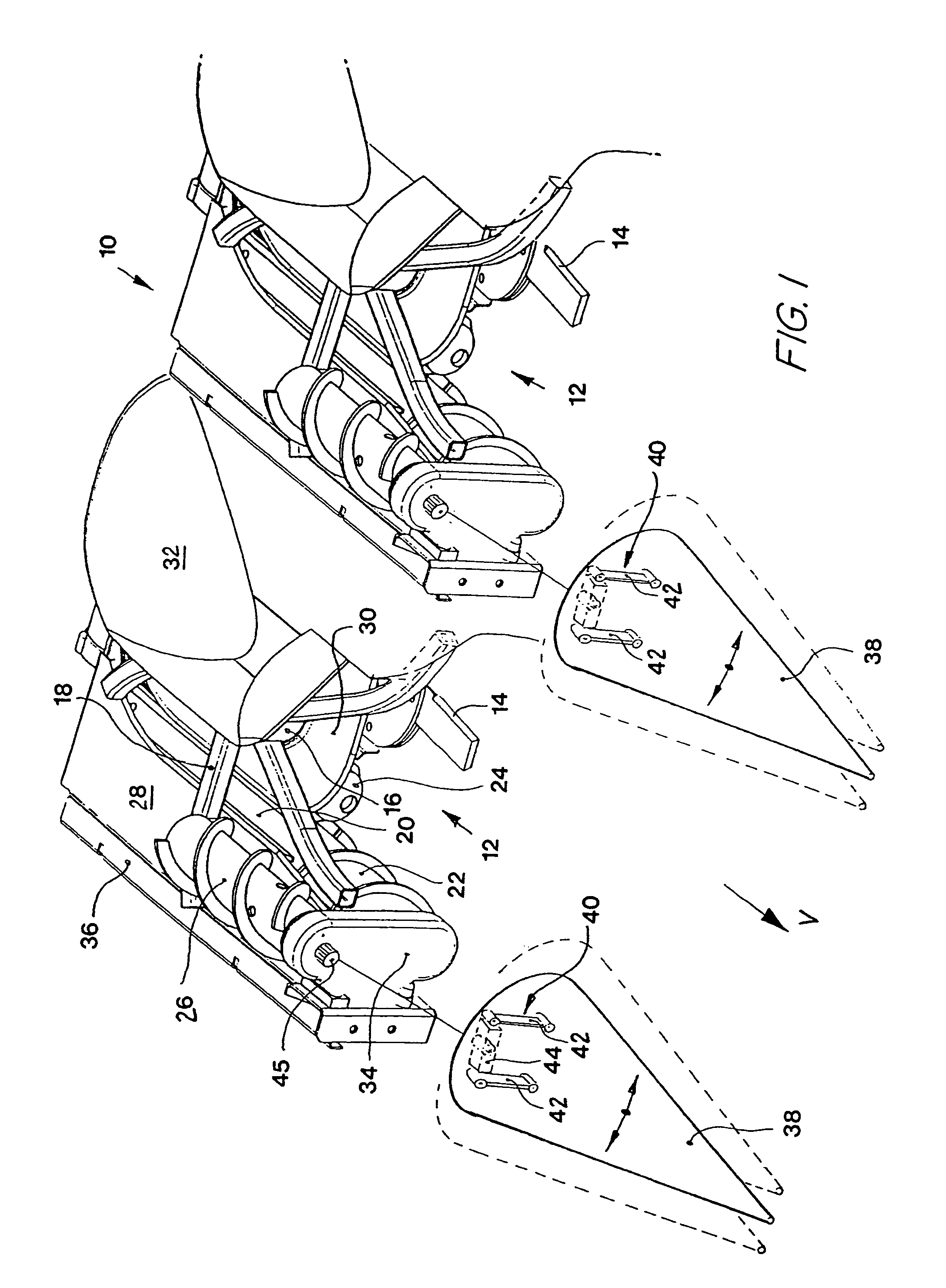
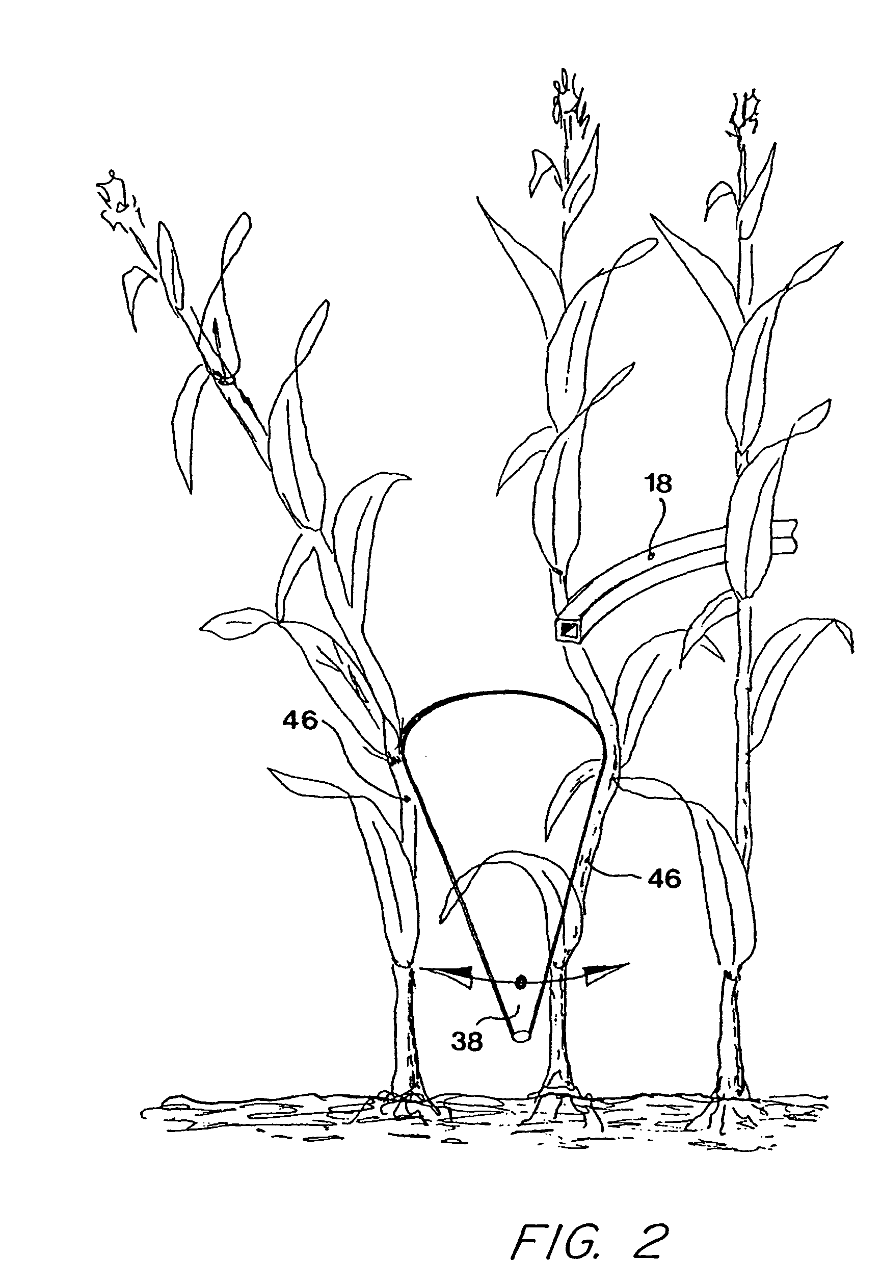
[0025]FIG. 3 shows a harvesting implement 10 according to the invention. The intake arrangements 12 are identical to those shown in FIG. 1, as is the parallelogram guidance linkage 40 on which the stalk dividers 48 are suspended so as to be able to move in the sideways direction. The stalk divider 48 differs from the stalk divider 38 of FIG. 1 only in the configuration of its surface. The stalk divider 48 is composed of individual truncated conical sections 50-56 that form steps in their transition regions with edges facing to the rear. Hence in the side view the surface of the stalk divider 48 is that of a saw-toothed cone. Thereby the result is that the plant stalk 46 that is forced downward by an adjacent stalk divider and rests upon the stalk divider 48 does not slide downward to the ground and is lost to the harvesting process, since it is in contact with a rear edge between the sections 50-56 and is prevented from sliding further. It is forced into the picking gap 20 by follow...

third embodiment

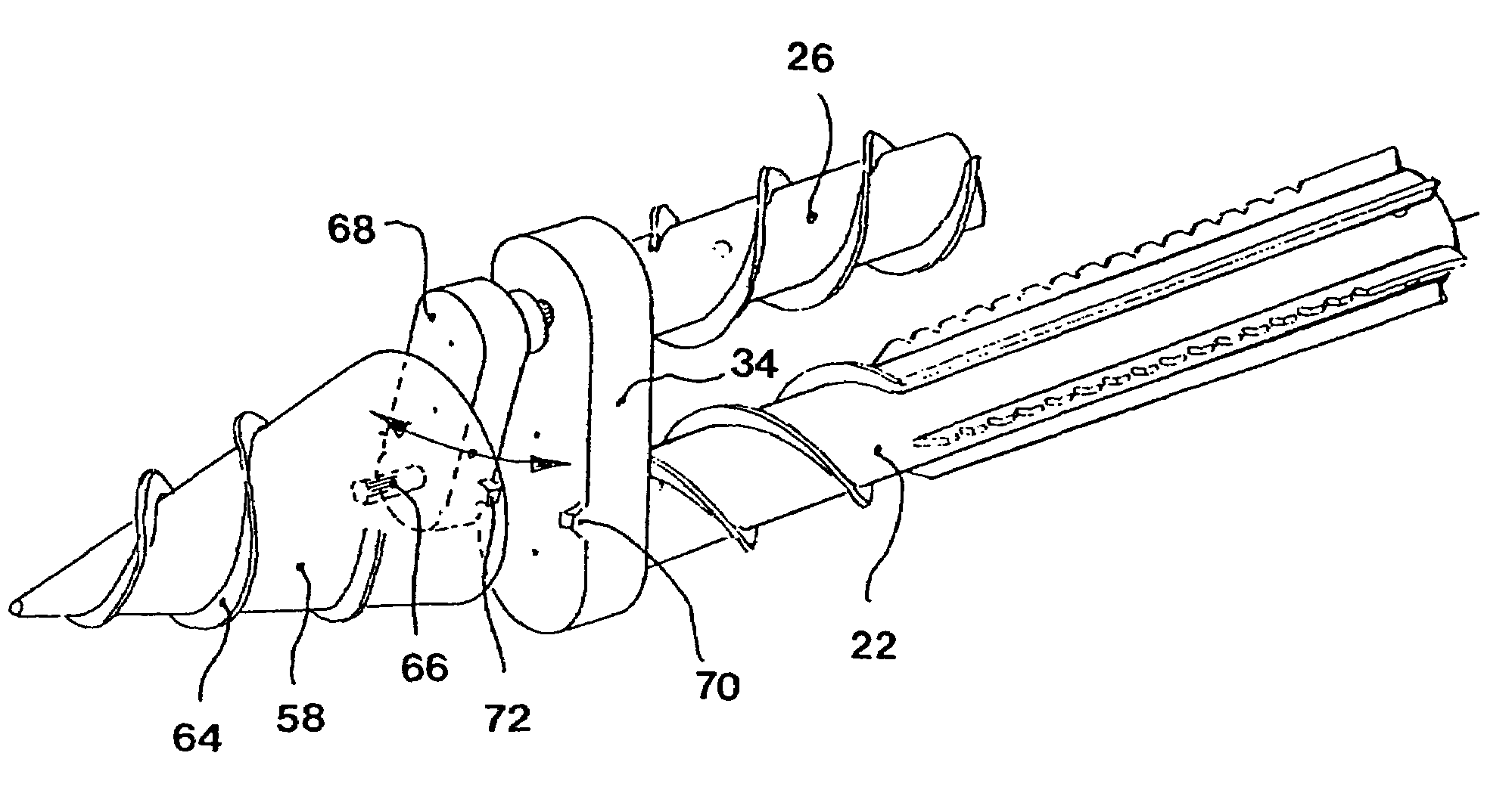
[0026]Finally, FIG. 4 shows a partial view of a harvesting implement 10 according to the invention. The intake arrangements 12 correspond to those shown in FIG. 1 and are therefore not shown here. In contrast to the first two embodiments, the stalk dividers 58 can be brought into rotation about their longitudinal axes. For this purpose, the rotational movement of the additional screw conveyor 26 is transmitted from the first gear 60 over a second gear 61 to a third gear 62, as can be seen in the sectional view through the retainer 68 of the stalk divider 58, which is shown in FIG. 5. The first gear 60 is rotatively supported in bearings in retainer 68 and is driven by a shaft extending from the front of the gearbox 34. The first gear 60 in turn drives the second and third gears 61 and 62 also rotatively supported by bearings in the retainer 68. The axes of rotation of the first, second and third gears 60, 61 and 62 are parallel to one another and extend in the forward direction V. T...


PUM


Abstract

A harvesting implement for the harvesting of stalk-like plants comprising an intake arrangement for taking up plants located on a field and a stalk divider arranged ahead of the intake arrangement in the forward direction. The crop divider is supported in bearings so that it is free to move relative to the intake arrangement when it is in its harvesting position. The stalk divider is free to move in the sideways direction, that extends transverse to the forward direction.

Description

FIELD OF THE INVENTION[0001]The present invention is directed to a harvesting implement for harvesting stalk-like plants, with at least one intake arrangement for the intake of stalk-like plants standing on a field and at least one stalk divider arranged in the forward operating direction ahead of the intake arrangement, that is supported in bearings so as to be able to move relative to the intake arrangement.BACKGROUND OF THE INVENTION[0002]EP 1 161 857 A describes a picker for the harvesting of stalk-like plants that includes a conveying element rotating about a vertical axis with drivers extending outward. The drivers grasp the plants standing on the fields and transport them in the sideways direction and to the rear, so that they reach a plucking slot. The plants are transported through the picking gap by means of two picking rolls arranged underneath the picking gap in interaction with the drivers of the conveying element. A further screw conveyor is arranged above the picking ...

Claims


Application Information

Patent Timeline
Patent Type & Authority Patents(United States)
IPC IPC(8): A01D45/02A01D63/02
CPCA01D45/021A01D63/02
Inventor RESING, ALFONSWUEBBELS, RICHARD
Owner MASCHFAB KEMPER
Why Eureka
Try Eureka