Slide caliper assembly and method of use

a technology of sliding calipers and assembly parts, applied in the field of sliding calipers, can solve the problems of only useful gages, no adequate handheld tools to measure the length of sheet metal walls, and skip the measurement of these walls

Inactive Publication Date: 2006-07-18
SPS INDS
View PDF19 Cites 19 Cited by
  • Summary
  • Abstract
  • Description
  • Claims
  • Application Information

AI Technical Summary

Problems solved by technology

Despite the sophisticated equipment available for the manufacture of custom fan trays, there is no adequate handheld tool to measure the lengths of sheet metal walls that are not bent at a right angle.
Typically during first article inspections the measurement of these walls are skipped since there is no method to easily measure walls with theoretical sharp corners.
Custom gages have to be designed and built for each application, and can be quite expensive.
Moreover, such gages are only useful for one application.
However, indirect measurement using a combination square can be slow and cumbersome, can rely heavily on operator technique, and can be very inaccurate.
However, these are complex, specialized equipment and tend to be quite expensive as compared to a hand held device such as, for example, slide calipers.
Such equipment would tend to be maintained in a fixed location such as a quality lab, and therefore those wanting to use the equipment on a shop floor or in design engineering offices would not have timely access to such equipment.
Moreover, the sophisticated metrology equipment would require specialized training and dedicated operators.

Method used


Image

  • Slide caliper assembly and method of use
  • Slide caliper assembly and method of use
  • Slide caliper assembly and method of use

Examples


second embodiment

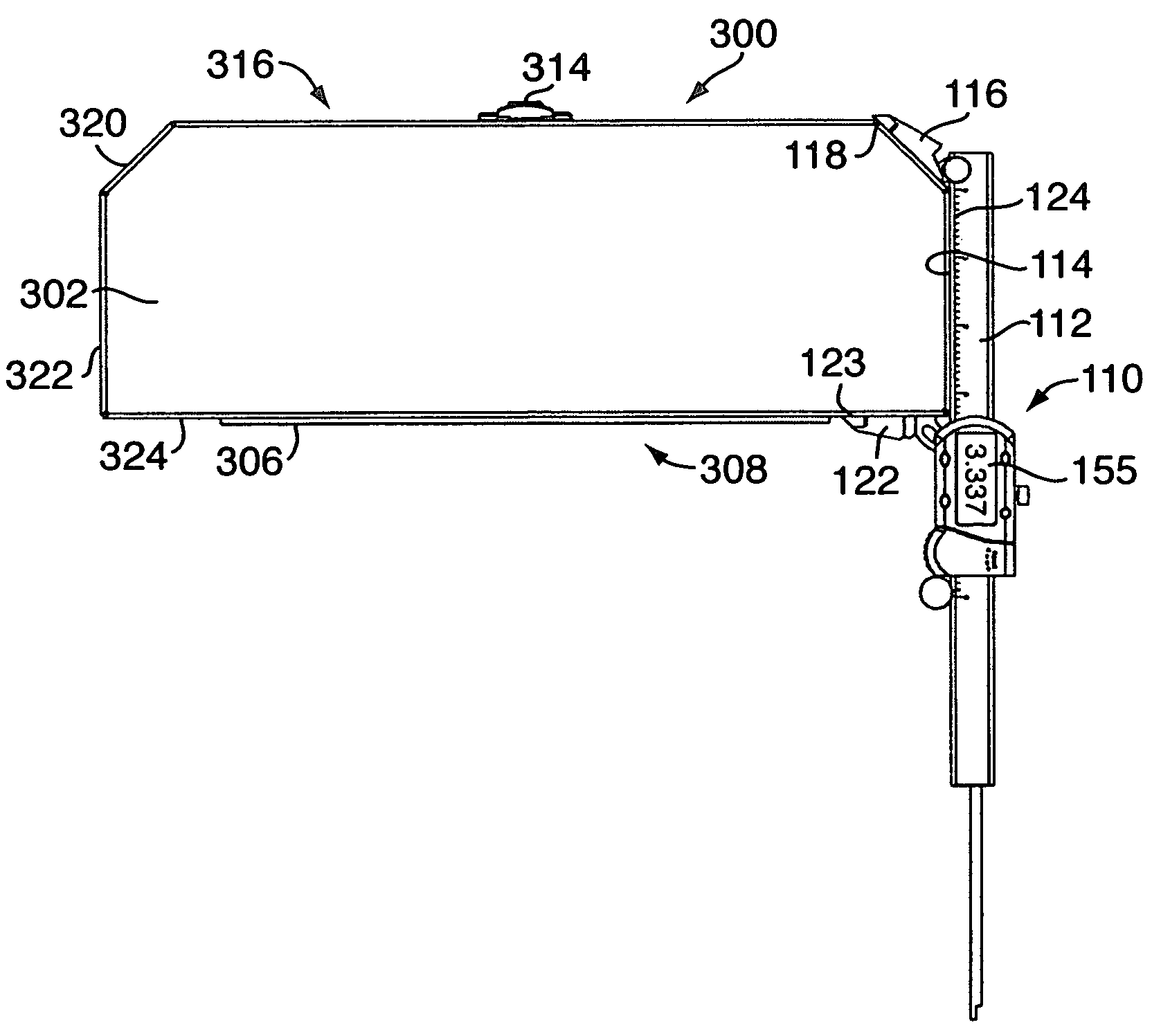
[0053]Referring now to FIGS. 11–17, a slide caliper in accordance with the present invention is generally indicated by the reference number 110. Like elements with the slide caliper 10 are labelled by like reference numbers preceded by “1”. The slide caliper 110 is used for measuring the length between two corners of an object wherein both corners might form theoretical sharp corners.

[0054]The slide caliper 110 comprises an elongated shaft 112 defining a first gaging surface 114. A first jaw 116 defining a second gaging surface 118 is pivotally coupled to the shaft 112 preferably adjacent to a first longitudinal end 120 of the shaft. A second jaw 122 defining a third gaging surface 123 is pivotally and slidably coupled to the shaft 112 for movement therealong. The shaft 112 preferably includes a graduated or linear measuring scale 124 therealong for measuring the distance between two corners of an object to be held between the gaging surface 118 of the first jaw 116 and the gaging s...

third embodiment

[0065]Referring now to FIGS. 18–24, a slide caliper in accordance with the present invention is generally indicated by the reference number 210. Like elements with the slide calipers 10 and 110 are labelled by like reference numbers preceded by “2”. The slide caliper 210 is generally the same as the slide caliper 110 shown in FIGS. 11–17 except that the slide caliper 210 further comprises a pair of additional jaws for measuring inner diameters, and further comprises means for making depth measurements. Accordingly, the slide caliper 210 will be explained only with respect to these additional features.

[0066]The slide caliper 210 comprises a third jaw 270 defining a fourth gaging surface 272 coupled to the shaft 212 preferably adjacent to the first longitudinal end 220 of the shaft. The third jaw 270 extends outwardly from the shaft 212 in a direction generally opposite to that of the first and second jaws 216, 222. The slide caliper further comprises a fourth jaw 274 defining a fifth...


PUM


Abstract

A slide caliper assembly comprises a caliper including a shaft defining a gaging surface. A first jaw is coupled to and a second jaw is slidably coupled to the shaft. Each jaw defines a gaging surface. One of the jaws is adjustably pivotable relative to the shaft about a pivot axis coinciding with an intersection of the gaging surface of the shaft and another axis extending along the associated gaging surface of one of the jaws. A case houses the caliper, and has a plurality of side edge sections defining a periphery of the case. One side edge section and an adjacent side edge section form a non-right angle therebetween such that the shaft can abut the side edge section, the first jaw can abut an adjacent side edge section, and the second jaw can abut another adjacent side edge section for calibrating or demonstrating the use of the caliper.

Description

CROSS-REFERENCE TO RELATED APPLICATION[0001]This is a continuation-in-part application of application Ser. No. 10 / 832,696, filed on Apr. 27, 2004, now U.S. Pat. No. 6,990,746 the disclosure of which is herein incorporated by reference in its entirety.FIELD OF THE INVENTION[0002]This invention relates generally to calipers, and more particularly to slide caliper assemblies for accurately measuring the length of structures between one or more theoretical sharp corners.BACKGROUND OF THE INVENTION[0003]One of the possible services in the fan and blower industry is to design and manufacture custom fan tray systems. The manufacturing of custom fan tray systems involves sheet metal manufacturing and assembly work. The dimensions to rounded edges (bends) of sheet metal parts are given to the theoretical sharp corners. The location of the theoretical sharp corner is also referred to as mold lines or apexes, and is defined as the location in space where two walls would intersect if they joine...

Claims


Application Information

Patent Timeline
Patent Type & Authority Patents(United States)
IPC IPC(8): G01B3/20G01B5/00G01B5/14
CPCG01B3/205
Inventor JOHN, WILLIAM THOMASPENNA, CHRISTOPHER PAULWATSON, DALE ALLAN
Owner SPS INDS
Why Eureka
Try Eureka