Optical disc changer

a technology of optical discs and changers, which is applied in the direction of data recording, instruments, recording head arrangements, etc., can solve the problems of deterioration of the reproduction of data from optical discs, user inconvenient repeating operations, etc., and achieve the effect of preventing the defective reproduction of optical discs

Inactive Publication Date: 2006-08-08
SAMSUNG ELECTRONICS CO LTD
View PDF20 Cites 0 Cited by
  • Summary
  • Abstract
  • Description
  • Claims
  • Application Information

AI Technical Summary

Benefits of technology

[0016]The foregoing and other objects of the present invention are achieved by providing an optical disc changer comprising a main body, a tray installed to be capable of sliding in the main body, a roulette rotatably installed at the tray and where a plurality of optical discs are accommodated, an optical pickup device to selectively reproduce one of the optical discs accommodated on the roulette, and a damping unit to absorb shock when the tray is loaded into and unloaded from the main body, so that defective reproduction of the optical disc is prevented.

Problems solved by technology

Since only one optical disc is accommodated on the tray of the optical disc drive, if a user wishes to reproduce data from a plurality of optical discs, the user must inconveniently repeat operations of ejecting the tray, placing a new optical disc that the user wishes to reproduce data from on the tray, and loading the tray in the disc drive.
However, there is no separate damping means to absorb shock, resulting in a deterioration of the reproduction of data from an optical disc.

Method used


Image

  • Optical disc changer
  • Optical disc changer
  • Optical disc changer

Examples


Embodiment Construction

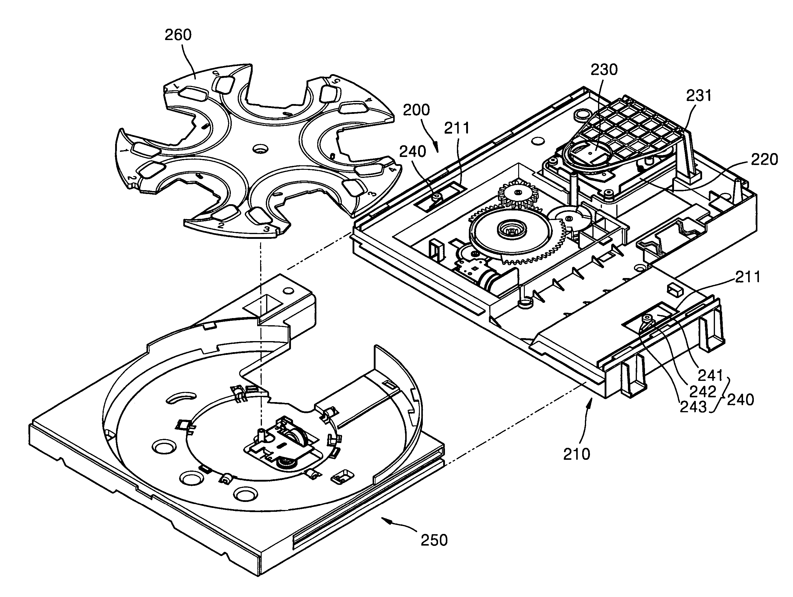
[0024]Referring to FIG. 3, an optical disc changer 200 according to the present invention includes a main body 210, a tray 250 slidably installed at the main body 210, a roulette 260 rotatably installed at the tray 250 and where a plurality of optical discs are accommodated, an optical pickup device 220 to selectively reproduce one of the optical discs accommodated on the roulette 260, and a clamp support 231 installed above the optical pickup device 220 to support a clamp plate 230 used to clamp the optical disc against the optical pickup device 220. Also, a damping unit 240 is provided to absorb shock when the tray 250 is loaded in or unloaded from the main body 210.

[0025]FIG. 4 is a side view of the optical disc changer shown in FIG. 3. FIG. 5 illustrates the operation of the damping unit 240 when the tray is loaded. FIG. 6 illustrates the operation of the damping unit 240 when the tray is unloaded.

[0026]Referring to FIGS. 4 through 6, the damping unit 240 absorbs shock when the ...


PUM

PropertyMeasurementUnit
movementaaaaaaaaaa
forceaaaaaaaaaa
elasticityaaaaaaaaaa

Abstract

An optical disc changer having a main body, a tray slidably installed in the main body, a roulette rotatably installed at the tray to accommodate a plurality of optical discs, an optical pickup device to selectively reproduce one of the optical discs accommodated on the roulette, and a damping unit to absorb shock when the tray is loaded in and unloaded from the main body to prevent defective reproduction of data from the optical disc.

Description

CROSS-REFERENCE TO RELATED APPLICATIONS[0001]This application claims the benefit of Korean Patent Application No. 2001-44201 filed on Jul. 23, 2001, in the Korean Industrial Property Office, the disclosure of which is incorporated herein by reference.[0002]This application is a continuation of U.S. patent application Ser. No. 10 / 029,984, filed on Dec. 31, 2001, now U.S. Pat. No. 7,020,886.BACKGROUND OF THE INVENTION[0003]1. Field of the Invention[0004]The present invention relates to an optical disc changer, and more particularly, to an optical disc changer in which the structure of a damping unit to absorb shock when a tray is loaded in or unloaded from a main body is improved.[0005]2. Description of the Related Art[0006]In general, optical disc drives reproduce information recorded on optical discs such as CDs or DVDs which are optical recording media by using optical pickup devices. When an optical disc is placed on a tray and loaded in a drive, a drive unit rotates the optical d...

Claims


Application Information

Patent Timeline
Patent Type & Authority Patents(United States)
IPC IPC(8): G11B17/24G11B17/22
CPCG11B17/226G11B17/24
Inventor KIM, GO-HYUNKIM, DONG-MANKIM, TAE-MYUN
Owner SAMSUNG ELECTRONICS CO LTD
Why Eureka
Try Eureka