Revolving battery reservoir system

a battery reservoir and revolving technology, applied in the field of revolving battery reservoir systems, can solve the problems of inconvenient battery expending and considerable delay of requirements

Inactive Publication Date: 2006-08-15
BARTON JAMES C
View PDF13 Cites 16 Cited by
  • Summary
  • Abstract
  • Description
  • Claims
  • Application Information

AI Technical Summary

Problems solved by technology

This requirement may introduce considerable delay between the time the batteries are expended and the time replacement batteries become available.
Furthermore, electrical devices typically do not include a mechanism for indicating the remaining lifetime of the batteries which power the device, frequenlty resulting in expending of the batteries at an inconveninent time.

Method used


Image

  • Revolving battery reservoir system
  • Revolving battery reservoir system
  • Revolving battery reservoir system

Examples


Embodiment Construction

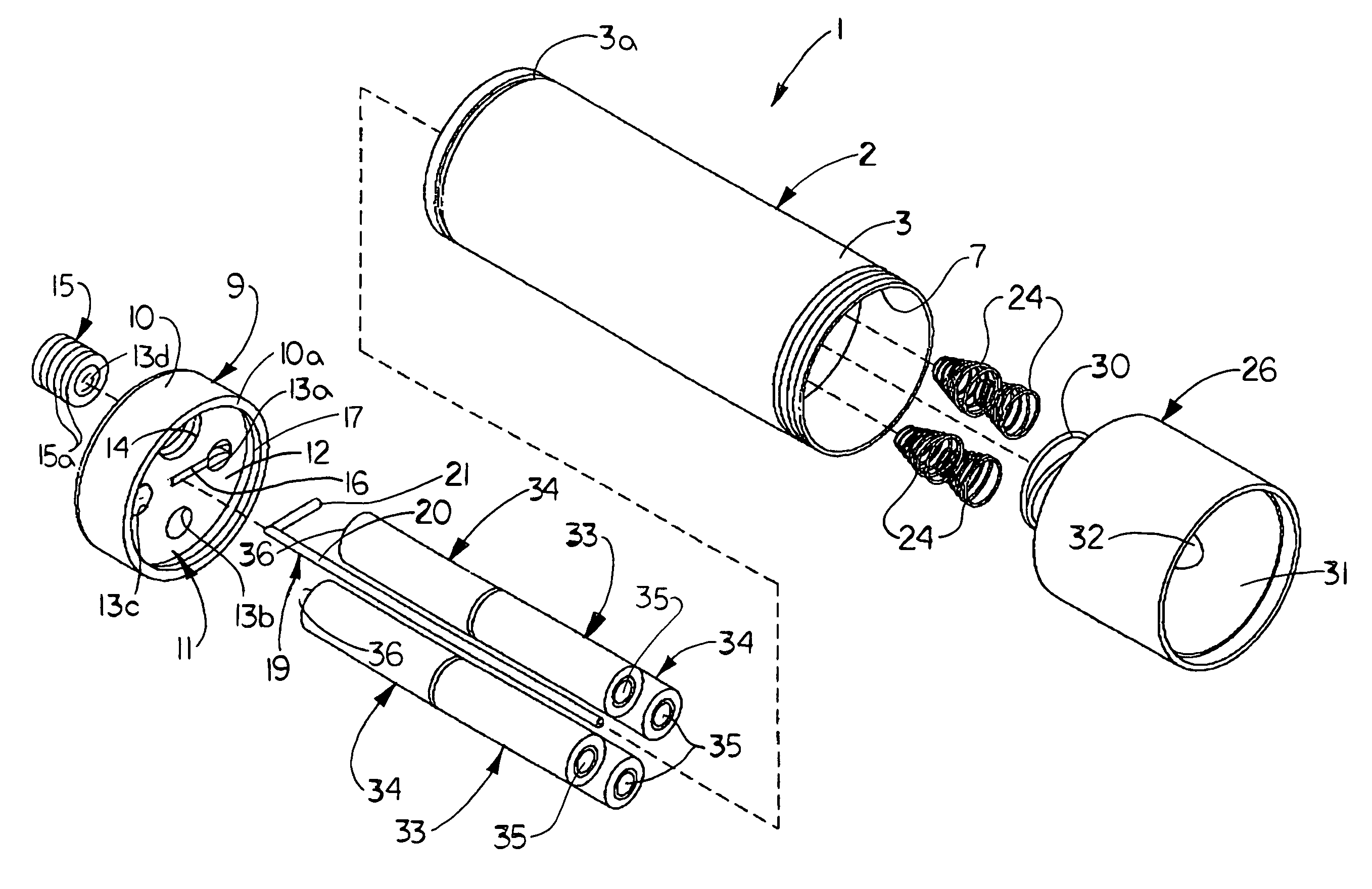
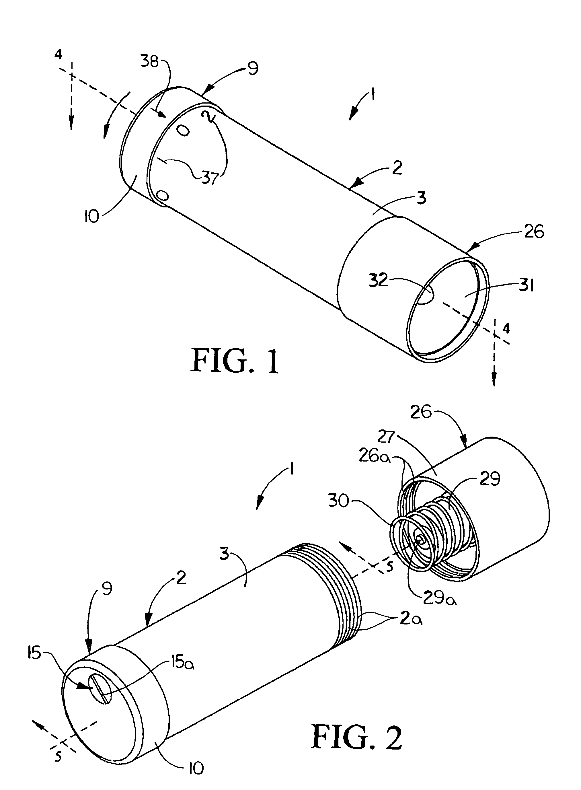
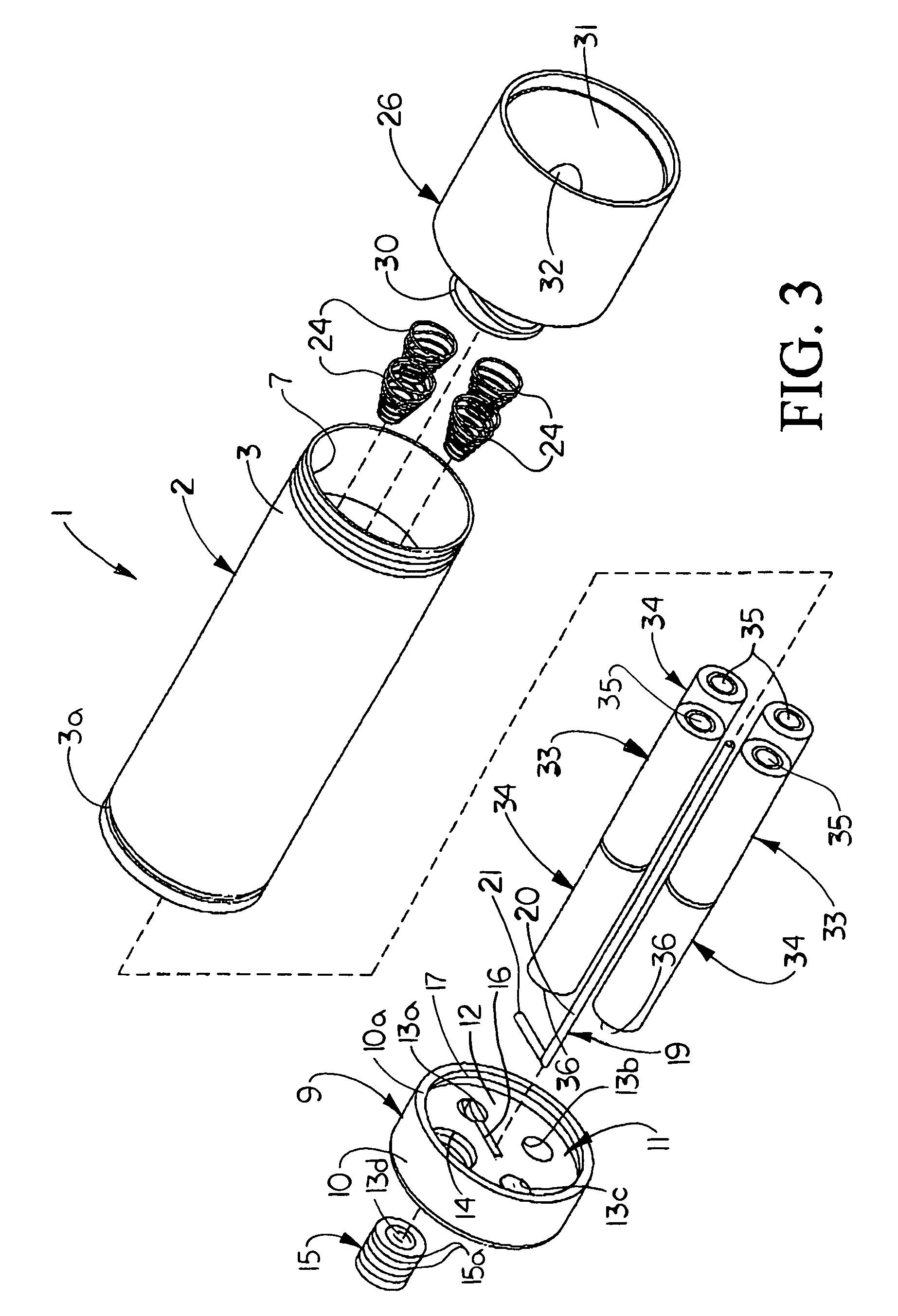
[0018]Referring initially to FIGS. 1–9 of the drawings, an illustrative embodiment of the revolving battery reserve system, hereinafter system, of the present invention is generally indicated by reference numeral 1. The system 1 includes an elongated, typically cylindrical system housing 2 having a body 3 through which extends multiple, adjacent battery cavities 6, as illustrated in FIG. 4. Each of the battery cavities 6 is adapted to receive a pair or set of multiple batteries, such as an interior battery 33 and an exterior battery 34, for example, each having a positive pole 35 and a negative pole 36. A central core 4 extends through the center of the system housing 2 and separates the battery cavities 6 from each other. A rod cavity 5, the purpose of which will be hereinafter described, extends through the core 4.

[0019]As illustrated in FIG. 2, a flashlight bulb housing 26 is removably attached to one end of the housing 2. Accordingly, housing threads 26a may be provided inside a...


PUM


Abstract

A revolving battery reservoir system is disclosed. The revolving battery reservoir system includes a system housing for containing multiple sets of batteries. A housing cap is rotatably mounted on the system housing. A contact rod is provided on the housing cap for contacting a selected one of the multiple sets of batteries responsive to rotation of the housing cap on the system housing. Multiple battery extension springs are provided in the system housing for engaging the multiple sets of batteries, respectively. An electrical device is provided in electrical contact with the multiple battery extension springs and the contact rod.

Description

FIELD OF THE INVENTION[0001]The present invention relates to battery-powering systems for flashlights and other electrical devices. More particularly, the present invention relates to a revolving battery reservoir system including multiple sets of batteries which can be sequentially selected to power an electrical device without the need for immediate replacement of expended batteries.BACKGROUND OF THE INVENTION[0002]Flashlights, radios and other electrical devices frequently require the use of portable electrical supplies in the form of batteries. When the batteries are expended, they must be replaced. This requirement may introduce considerable delay between the time the batteries are expended and the time replacement batteries become available. Furthermore, electrical devices typically do not include a mechanism for indicating the remaining lifetime of the batteries which power the device, frequenlty resulting in expending of the batteries at an inconveninent time.[0003]Therefore...

Claims


Application Information

Patent Timeline
Patent Type & Authority Patents(United States)
IPC IPC(8): H02J7/00
CPCH01M6/425H01M2/105H01M50/213
Inventor BARTON, JAMES C.
Owner BARTON JAMES C
Why Eureka
Try Eureka