Cutting edges for wire cutters

a wire cutter and cutting edge technology, applied in the field of wire cutters, can solve the problems of not strengthening the cutting efficiency and requiring a lot of effort to cut wires,

Active Publication Date: 2006-08-22
HSIEH CHIH CHING
View PDF7 Cites 11 Cited by
  • Summary
  • Abstract
  • Description
  • Claims
  • Application Information

AI Technical Summary

Problems solved by technology

Besides, the cutting edge has a fixed curvature and tilt angle which cannot reinforce the efficiency of cutting and requires a lot of efforts to cut the wires.

Method used


Image

  • Cutting edges for wire cutters
  • Cutting edges for wire cutters
  • Cutting edges for wire cutters

Examples


Embodiment Construction

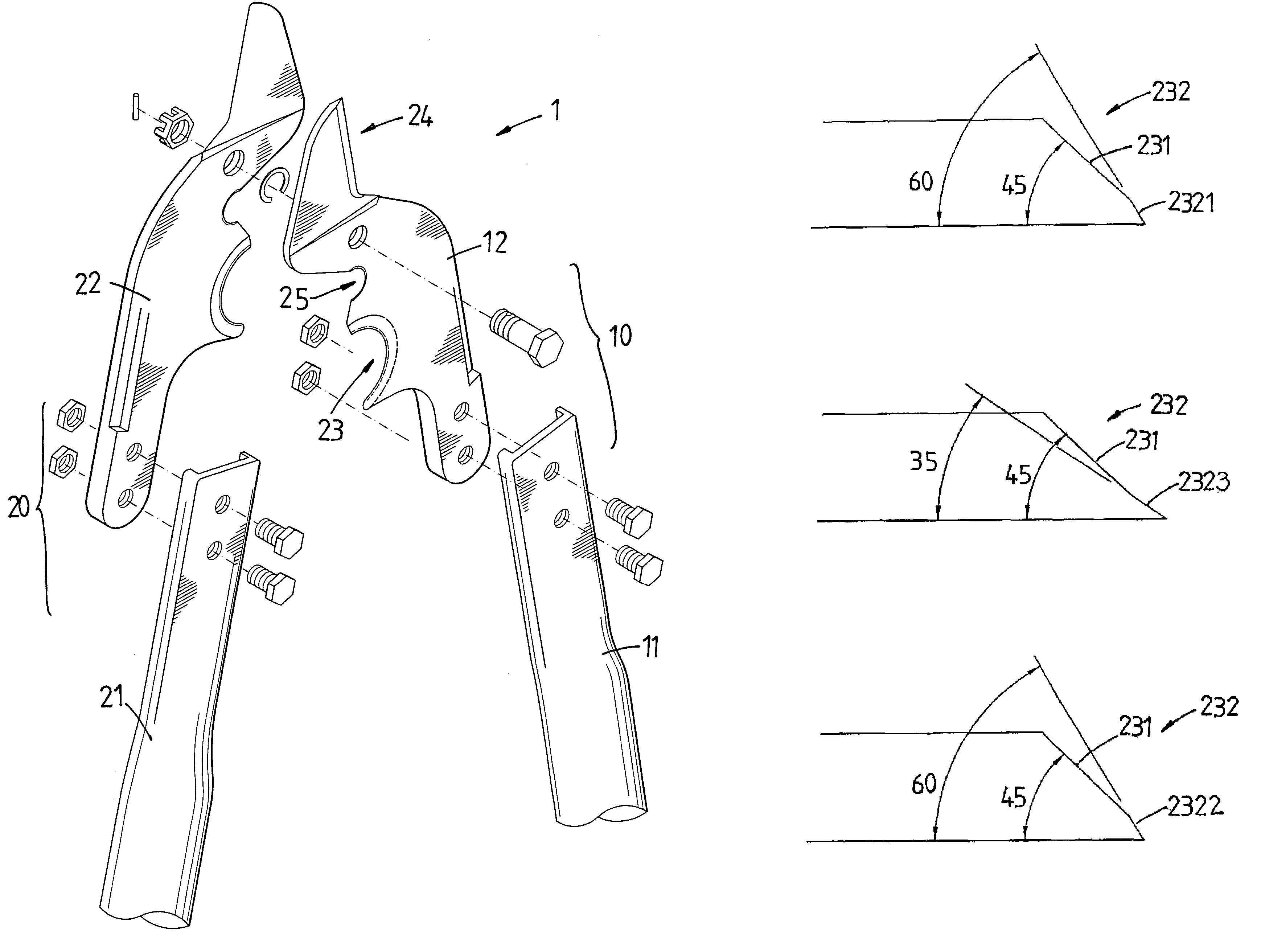
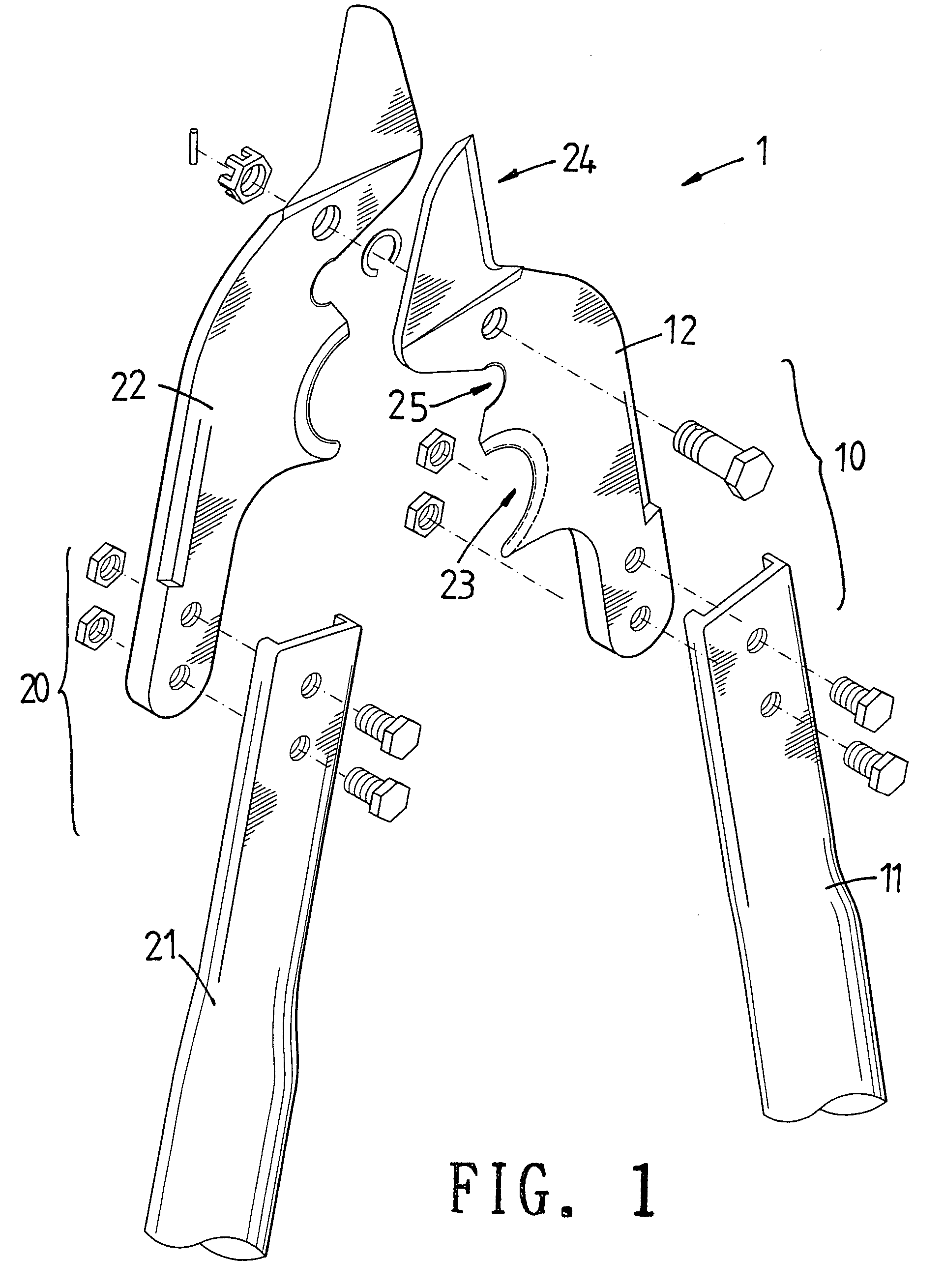
[0015]Referring to FIGS. 1, 2, 3A, 3B, 3C, 4 and 5, the wire cutter of the present invention is composed of two halves 10, 20 and each half 10 / 20 comprises a handle 11 / 21 and a jaw 12 / 22 connected to the handles 11 / 21 corresponding thereto. The two jaws 12, 22 are pivotably connected with each other by a bolt or a rivet such that when the two handles 11, 21 are opened wide, the two jaws 12, 22 are opened wide.

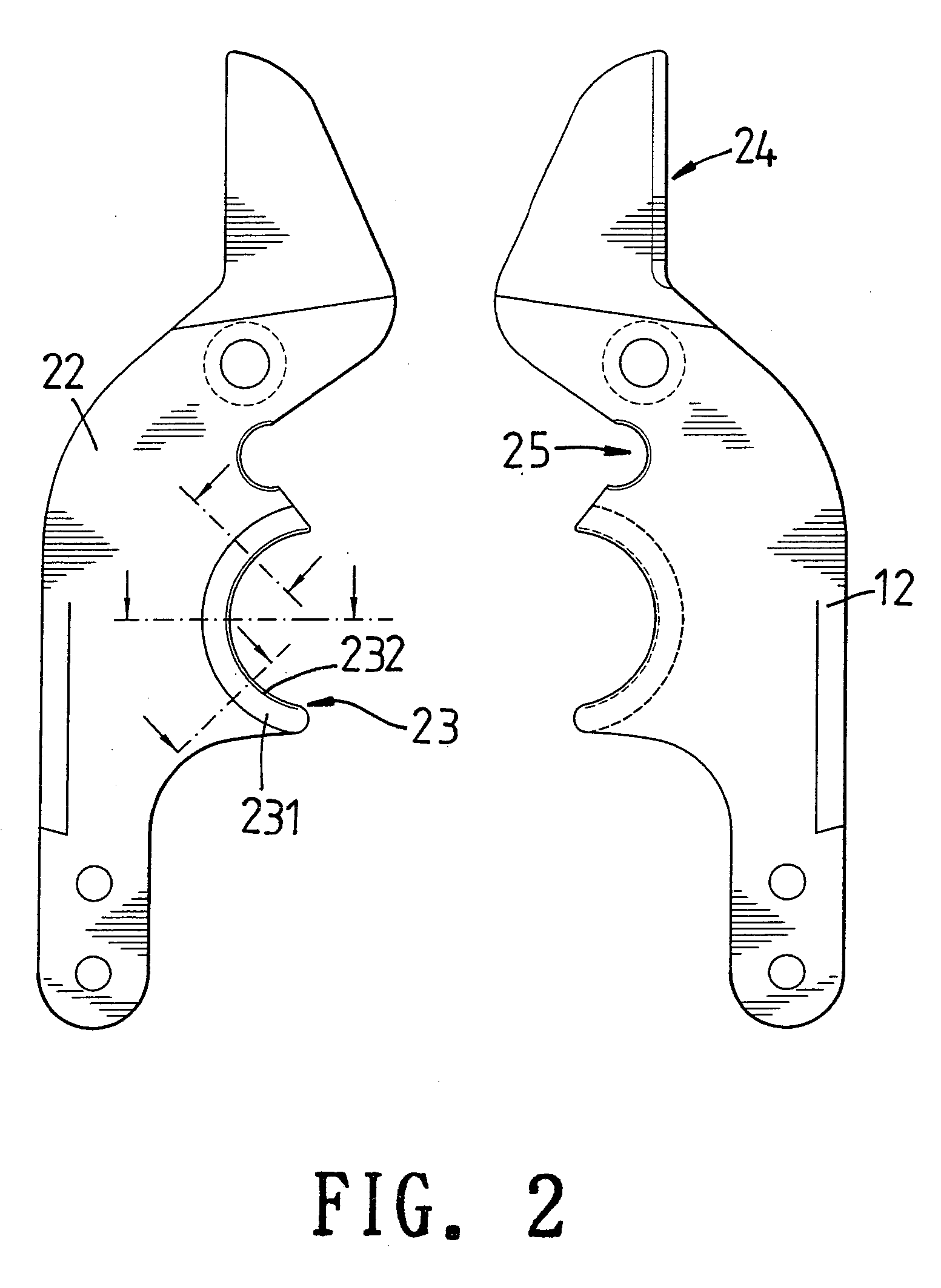
[0016]Each jaw 12 / 22 includes a straight cutting edge 24, a peeling edge 25 and a curve cutting edge 23 which includes a base portion 231 and a cutting portion 232 which is connected to the base portion 231. The cutting portion 232 includes a first section 2321, a second section 2322 and a third section 2323 which is located between the first and second sections 2321, 2322.

[0017]Each of the first section 2321 and the second section 2322 has a first side surface and a second side surface. A first angle of 60 degrees is defined between the first side surface and the second side s...


PUM

PropertyMeasurementUnit
angleaaaaaaaaaa
angleaaaaaaaaaa
angleaaaaaaaaaa

Abstract

A wire cutter includes two jaws pivotably connected with each other and each jaw has a curve cutting edge which includes a cutting portion which includes a first section, a second section and a third section which is located between the first and second sections. Each of the first section and the second section has a first side surface and a second side surface, and a first angle of 60 degrees is defined between the first side surface and the second side surface. The third section has a third side surface and a fourth side surface, a second angle of 35 degrees is defined between the third side surface and the fourth side surface. The wires are pushed toward the second sections and cut by the second sections.

Description

FIELD OF THE INVENTION[0001]The present invention relates to a wire cutter wherein the cutting edge includes three cutting sections with different tilt angles.BACKGROUND OF THE INVENTION[0002]A conventional wire cutter includes two jaws connected to two handles which are pivotably connected with each other such that the two jaws can be separated by pivoting the two handles apart, and be moved toward each other to cut the wires between the two jaws by closing the two handles together. Generally, the cutting edge for cutting the wires of each jaw is designed to be a curve cutting edge so as to cut a bundle of wires which includes plastic sheath and metal core wire. Nevertheless, during cutting, the wires are pushed toward two ends of the cutting edges because of the movement of the two jaws and the two handles are maintained to be opened wide. Therefore, the user has to open his hand to push the two handles toward each other to cut the wires. Besides, the cutting edge has a fixed curv...

Claims


Application Information

Patent Timeline
Patent Type & Authority Patents(United States)
IPC IPC(8): B21F13/00
CPCB23D29/023
Inventor HSIEH, CHIH-CHING
Owner HSIEH CHIH CHING
Why Eureka
Try Eureka