Hinge device

a technology of hinges and hinges, which is applied in the direction of wing openers, multi-purpose tools, constructions, etc., can solve the problems of door panel slamming and the like, and avoid the effect of slamming the door panel during the closing of the sam

Active Publication Date: 2006-08-29
LIN MING JENG
View PDF6 Cites 68 Cited by
  • Summary
  • Abstract
  • Description
  • Claims
  • Application Information

AI Technical Summary

Problems solved by technology

The conventional hinge device is disadvantageous in that since the door panel 11 is urged by the torsion spring 23, slamming of the door panel 11 tends to occur during closing of the same.

Method used


Image

  • Hinge device
  • Hinge device
  • Hinge device

Examples


Embodiment Construction

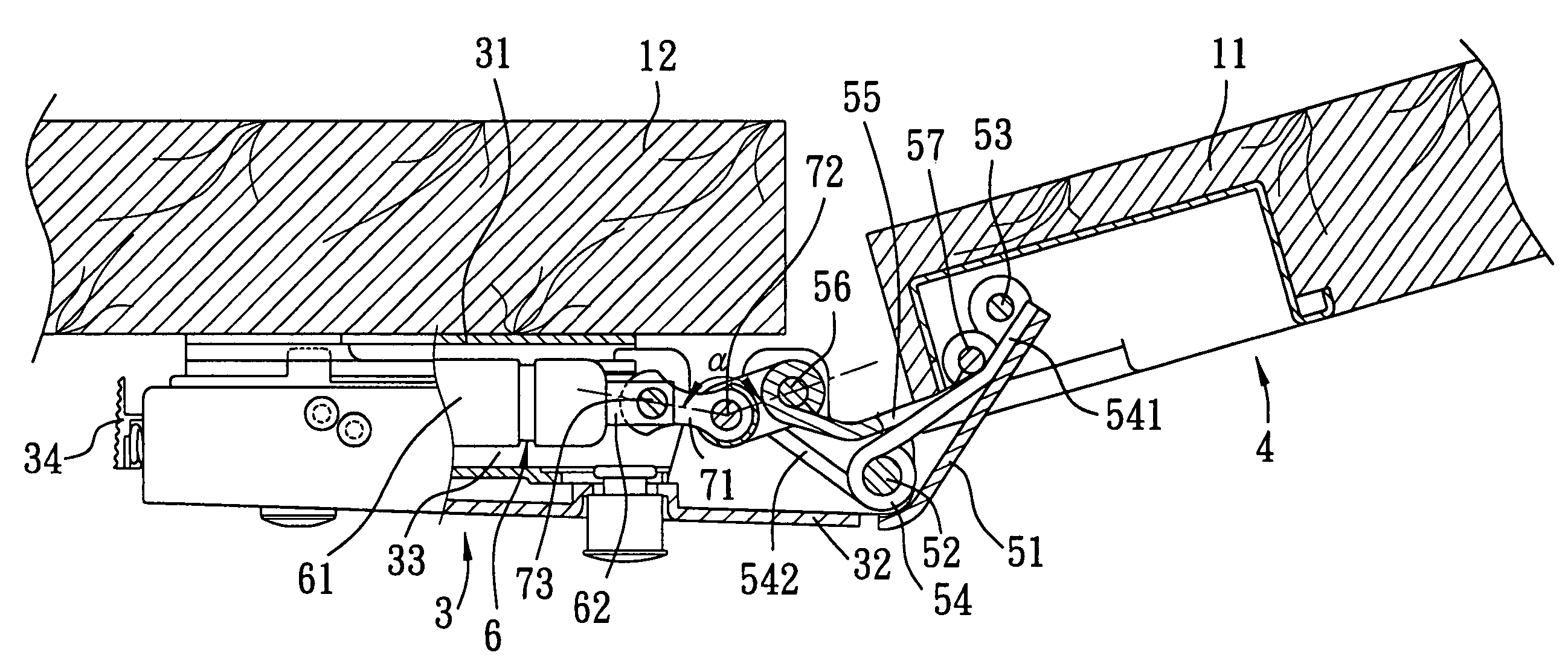
[0017]FIGS. 4 to 6 illustrate the first preferred embodiment of a hinge device according to the present invention, which is adapted to connect a door panel 11 to a door frame 12.

[0018]The hinge device includes: a frame bracket 3 adapted to be secured to the door frame 12; a door bracket 4 adapted to be secured to the door panel 11; spaced apart first and second links 51, 55, the first link 51 being pivoted to the frame bracket 3 through a pivot pin 52 and to the door bracket 4 through a pivot pin 53, the second link 55 being pivoted to the frame bracket 3 through a pivot pin 56 and to the door bracket 4 through a pivot pin 57 (which is connected to the pivot pin 53 to form a U-shaped rod), the first and second links 51, 55 permitting pivoting movement of the door panel 11 together with the first and second links 51, 55 relative to the door frame 12; an urging member 54 for urging the door panel 11 to move from an opened position (see FIG. 5) toward a closed position (see FIG. 6) rel...


PUM


Abstract

A hinge device includes a frame bracket adapted to be secured to a door frame, a door bracket adapted to be secured to a door panel, first and second links pivoted to the frame bracket and the door bracket, an urging member for urging the door panel to move from an opened position toward a closed position relative to the door frame, and a damping member adapted to be secured to the door frame and connected movably to the second link through a transmission link so as to damp pivoting movement of the door panel relative to the door frame.

Description

BACKGROUND OF THE INVENTION[0001]1. Field of the Invention[0002]This invention relates to a hinge device, more particularly to a hinge device with a damping member for damping pivoting movement of a door panel relative to a door frame.[0003]2. Description of the Related Art[0004]FIGS. 1 to 3 illustrate a conventional hinge device that includes a door bracket 14 secured to a door panel 11, and a frame bracket 13 pivoted to the door bracket 14 and secured to a door frame 12 so as to permit pivoting movement of the door panel 11 relative the door frame 12. The hinge device further includes a first link 21 pivoted to the door bracket 14 through a first pivot pin 26 and to the frame bracket 13 through a second pivot pin 24, a second link 22 pivoted to the door bracket 14 through a third pivot pin 27 and to the frame bracket 13 through a fourth pivot pin 25, and a torsion spring 23 sleeved around the second pivot pin 24 and having a first end 231 secured to the frame bracket 13, and a sec...

Claims


Application Information

Patent Timeline
Patent Type & Authority Patents(United States)
IPC IPC(8): E05F1/08E05D11/10E05F1/12E05F3/20
CPCE05D11/1021E05F1/1215E05F5/006E05Y2201/21E05Y2201/256E05Y2201/264Y10T16/5383E05Y2600/45E05Y2900/20Y10T16/304Y10T16/53832Y10T16/2771E05Y2201/626
Inventor LIN, MING-JENG
Owner LIN MING JENG
Why Eureka
Try Eureka