Adjustable kickstand with reinforced parking position lock

a technology of parking position lock and adjustable kickstand, which is applied in the direction of bicycle stands, bicycle equipment, furniture parts, etc., can solve the problems of reducing the length affecting the stability of the second member, so as to achieve the effect of lengthening the longitudinal extent of the second member

Inactive Publication Date: 2006-08-29
GRIGGS TERRANCE M
View PDF20 Cites 14 Cited by
  • Summary
  • Abstract
  • Description
  • Claims
  • Application Information

AI Technical Summary

Benefits of technology

[0009]In another aspect, the present invention is an adjustable kickstand having a first member and a second member relatively extendable from the first member. The first member includes a first internal chamber longitudinally formed therein into which a proximal end of the second member is inserted and is coupled to the first member. Interposed between the proximal end of the second member and a wall of the internal chamber of the first member is a resilient member, such as a spring, and at least one spacing member. The at least one spacing member effectively lengthens the longitudinal extent of the second member. When properly installed, a clamping device will attach the kickstand to a vehicle and spacers are added onto the second member until a footpad at the distal end thereof is in contact with the parking surface while the vehicle is supported upright at a predetermined tilt.

Problems solved by technology

For many kickstand configurations, these functions are seemingly mutually exclusive, i.e., the more immovable the kickstand is from its locked parking position, the more difficult it is to retract the kickstand into its stowage position.
Whereas, the stand of Bookbinder is convenient to operate and is reasonably secure against accidental retraction, the mechanism is extremely complex and involves an electric motor.
Not only do these factors weigh heavily on the cost of the stand, but the vehicle may also be rendered unsafe to operate should an electrical failure occur in the circuit of the stand while the stand is in its extended parking position.
Ruth uses gravitational forces to reinforce the locked relationship between the extendable leg and the outer member to prevent longitudinal retraction of the stand, but does not securely lock the kickstand in the parking position.
As such, if the vehicle were to be “bumped” from the rear, it is possible for the kickstand to collapse, which, in the case of vehicles such as motorcycles, may result in substantial damage.

Method used


Image

  • Adjustable kickstand with reinforced parking position lock
  • Adjustable kickstand with reinforced parking position lock
  • Adjustable kickstand with reinforced parking position lock

Examples


Embodiment Construction

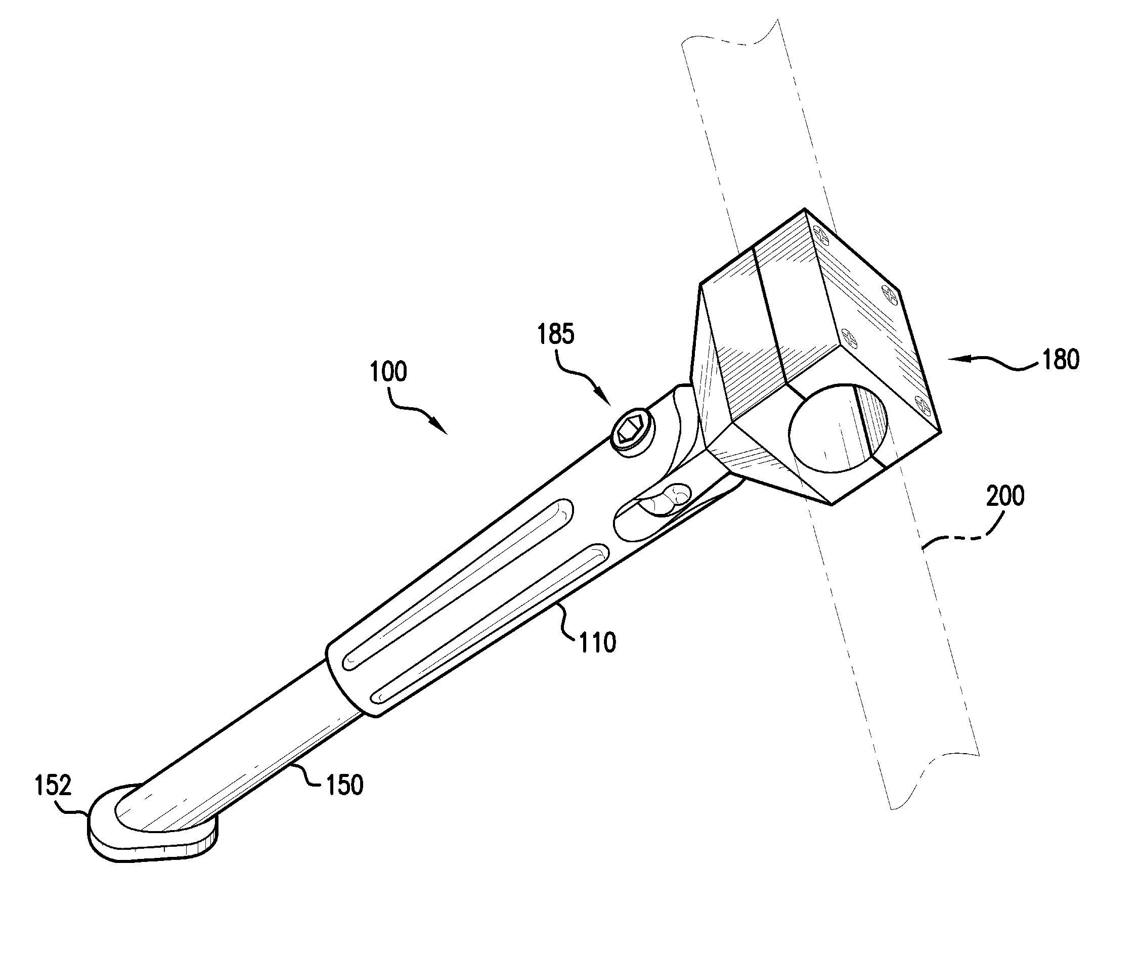
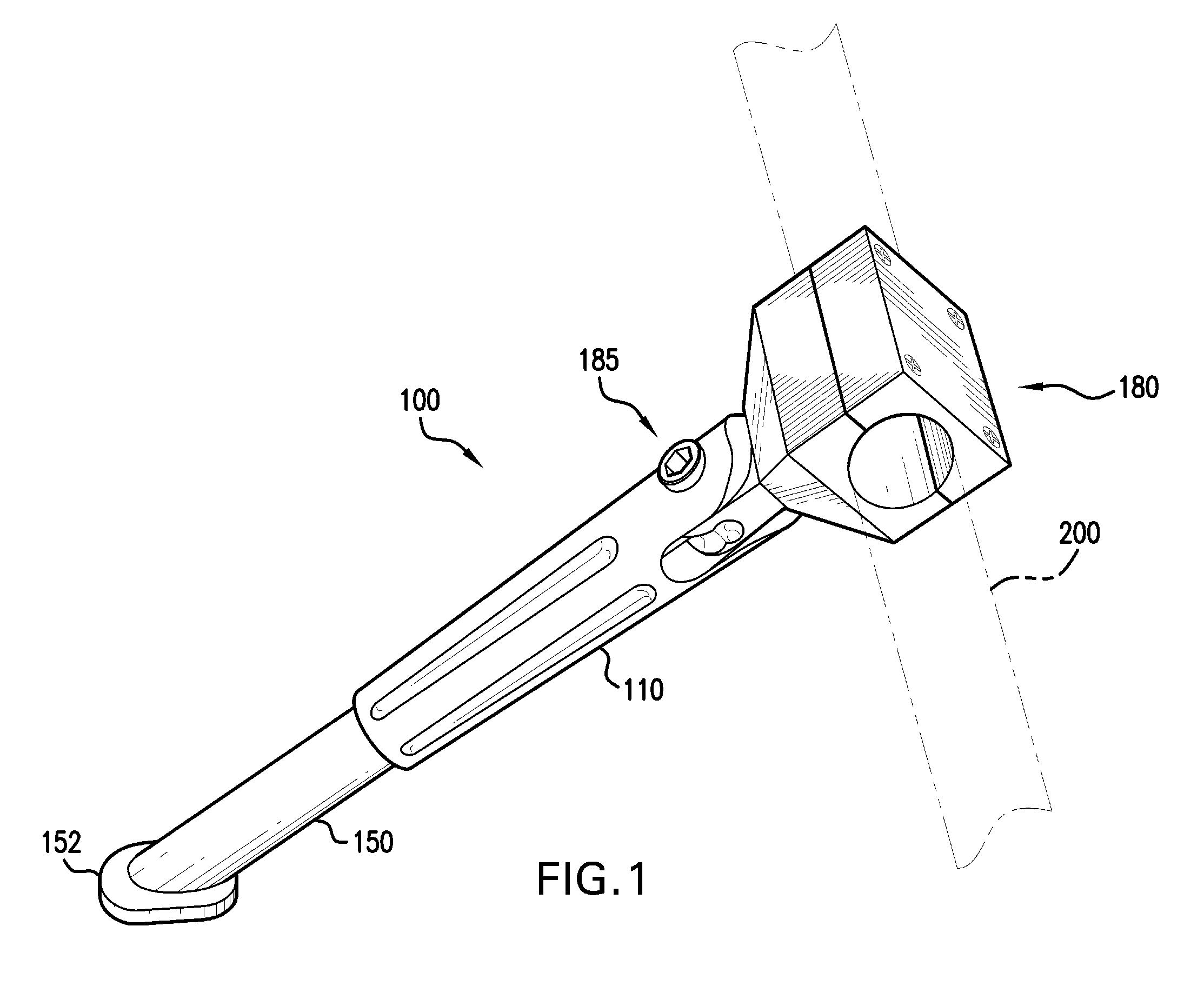
[0016]Referring to FIG. 1, there is shown in overall view an exemplary embodiment of the adjustable kickstand of the present invention. As is shown in the Figure, the kickstand 100 is mechanically coupled to a frame member 200 of a vehicle by clamping means 180. Note that while clamping means 180 is illustrated to conform to the circular cross-section of frame member 200, it should be clear that other general attachment configurations exist that fall within the scope of the present invention.

[0017]In accordance with the objects of the present invention, certain embodiments thereof include a fixed kickstand body 110 and an extendable leg 150. Kickstand 100 is in contact with the parking surface at support foot 152 which is mechanically coupled to the distal end of extendable leg 150.

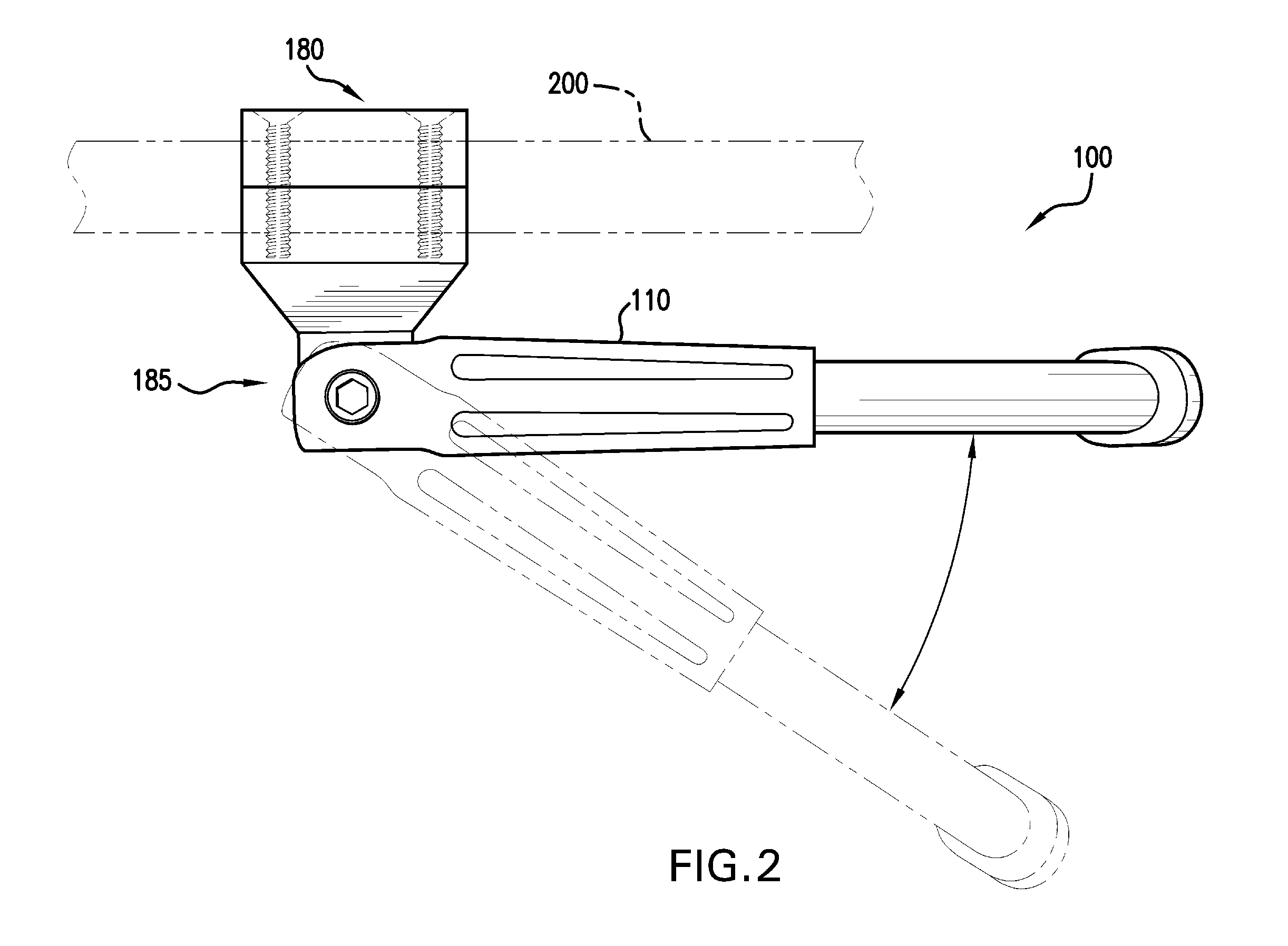
[0018]In similar operation to kickstands of the prior art, kickstand 100 is operable via pivoting means 185 to be stowed when not in use for stabilizing the vehicle. The stowage of kickstand 100 is illust...


PUM


Abstract

An adjustable kickstand is constructed from a fixed kickstand body (110) and an extendable leg (150). The extendable leg (150) is effectively lengthened by the use of at least one spacing element (120a–120e). When at the proper length, the kickstand is mounted to a vehicle so as to prop the vehicle up at a predetermined angle, while providing sufficient force on a support foot (152) on a distal end of extendable leg (150) to prevent slippage on a parking surface.

Description

FIELD OF THE INVENTION[0001]The invention described herein is related to an apparatus for propping upright a land vehicle when not in use. Specifically, the invention relates to kickstands. More specifically, the present invention relates to kickstands which include locking mechanisms operable to prevent accidental retraction of the stand from a parking position.BACKGROUND OF THE INVENTION[0002]As is widely known, a kickstand is a device for propping a vehicle, which would otherwise fall over, in an upright position, and which can be retracted for stowage when the vehicle is to be operated. Thus, it is desirable for a kickstand to be securely lockable in a parking position, while, at the same time, being easily retracted into its stowage position. For many kickstand configurations, these functions are seemingly mutually exclusive, i.e., the more immovable the kickstand is from its locked parking position, the more difficult it is to retract the kickstand into its stowage position.[0...

Claims


Application Information

Patent Timeline
Patent Type & Authority Patents(United States)
IPC IPC(8): B62H1/02
CPCB62H1/06B62H1/02
Inventor GRIGGS, TERRANCE M.
Owner GRIGGS TERRANCE M
Why Eureka
Try Eureka