Motor controller

a technology of motor controller and control panel, which is applied in the direction of electric generator control, dynamo-electric converter control, dynamo-electric gear control, etc., can solve the problems of insufficient or excessive compensation amount of phase and direction of current depending on the usage environment, torque ripple, vibration, etc., and achieve high-quality compensation

Inactive Publication Date: 2006-09-05
TOYODA MASCH WORKS LTD +2
View PDF7 Cites 24 Cited by
  • Summary
  • Abstract
  • Description
  • Claims
  • Application Information

AI Technical Summary

Benefits of technology

[0009]Accordingly, it is an objective of the present invention to provide a motor controller that performs highly accurate compensation without delay.
[0012]According to the above configuration, since DUTY instruction values are corrected independently for each phase and its direction of current, current distortion due to dead time is accurately compensated for even if the response speeds of the switching elements forming the PWM inverter vary among the individuals.
[0013]Further, an actual DUTY value that corresponds to the DUTY instruction value is detected, and a difference value between the DUTY instruction value before correction and the actual DUTY value is computed, so that insufficiency or excess of the compensation amount used for correcting the DUTY instruction value is obtained. Then, the difference value is added to the compensation amount that has been used for correction to determine a new compensation amount. The compensation amount that has been used for correction is renewed with the new compensation amount. Thus, the subsequent dead time compensation will be executed with higher accuracy.
[0015]Further, since the compensation amount stored in the memory section is successively renewed with a newly determined compensation amount, the compensation amount does not need to be determined at initialization (when determining factory default settings). For example, all the compensation amounts for all the phases and the all the directions of current may be set to zero. This eliminates the setting process and thus reduces the manufacturing costs.

Problems solved by technology

However, the dead time causes errors to occur between a voltage command value and an output voltage of the PWM inverter.
This in turn creates torque ripples, vibrations, and current distortion, which can cause noise.
Therefore, the above introduced method in which the DUTY instruction value αx is corrected using the dead time compensation amount β, compensation amounts of the phases and directions of current can be insufficient or excessive depending on the usage environment.
This may lead to a situation where current distortion due to dead time is not prevented with accuracy.
On the other hand, the method using feedback control, a delay is inevitable in providing compensation.

Method used


Image

  • Motor controller
  • Motor controller
  • Motor controller

Examples


Embodiment Construction

[0022]Hereinafter, a preferred embodiment according to the present invention will be described.

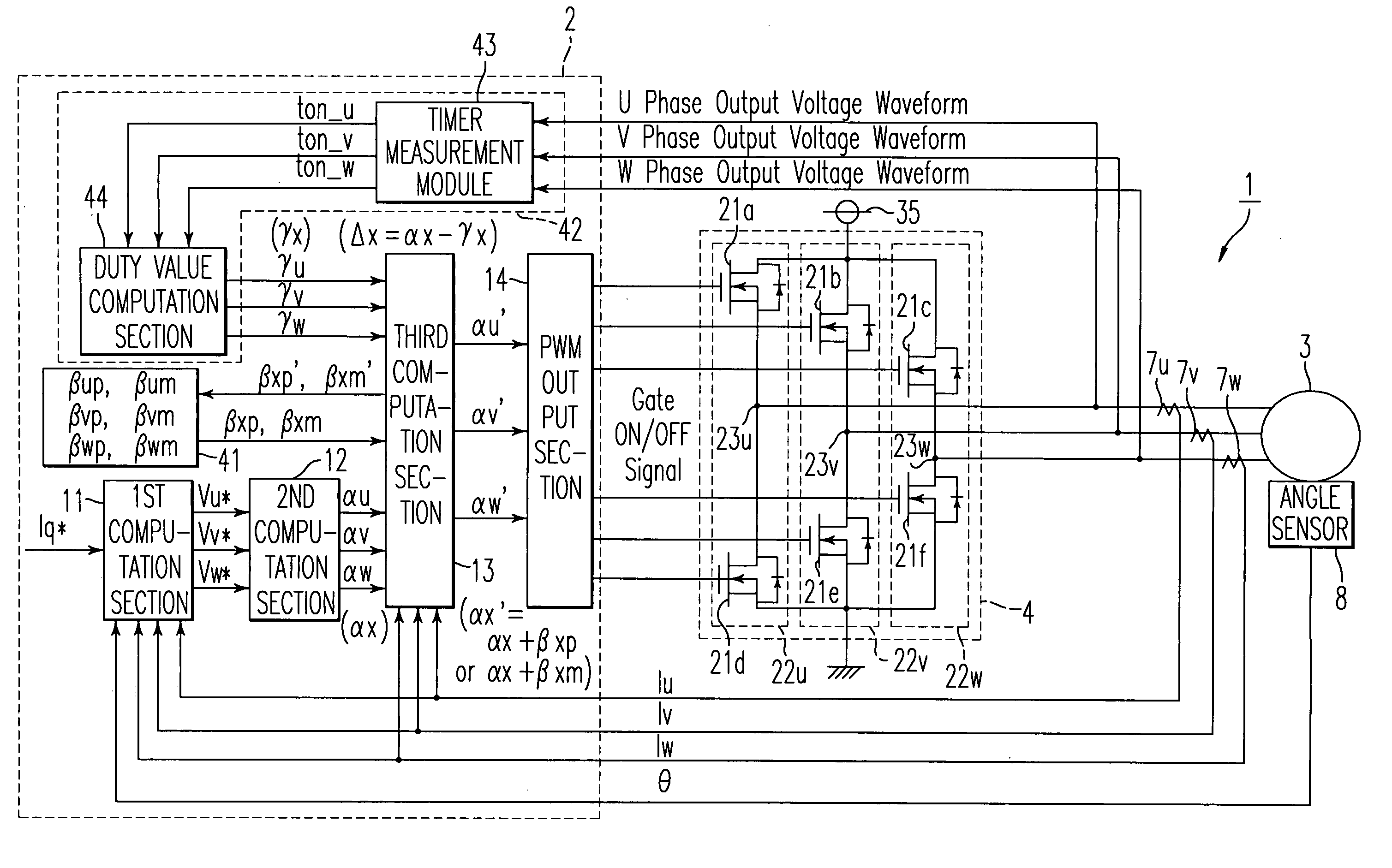
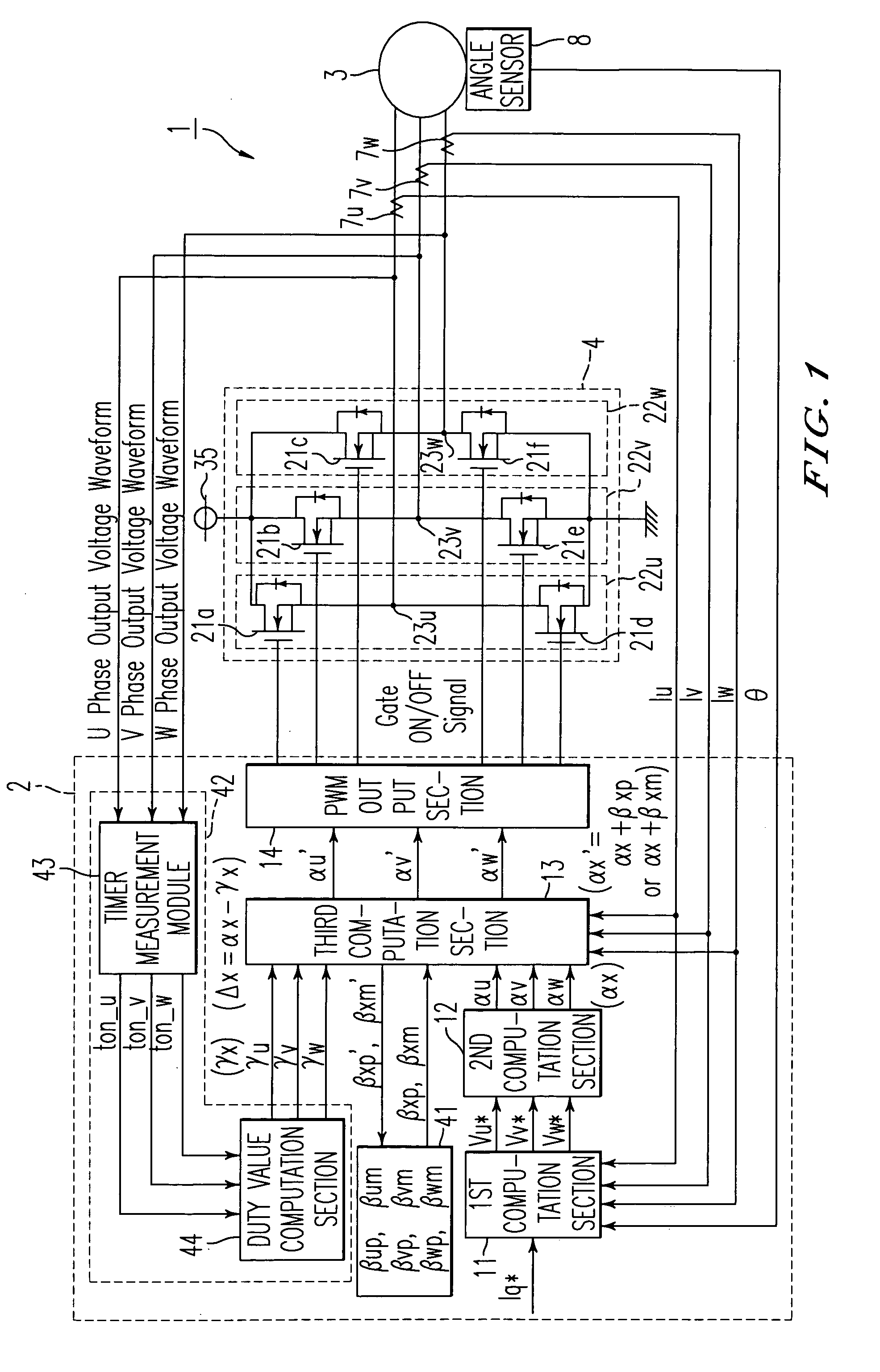
[0023]As shown in FIG. 1, a motor controller 1 includes a microcomputer 2 that outputs gate ON / OFF signals and a PWM (pulse-width modulation) inverter 4 that supplies three-phase driving power to a brushless motor 3 based on the gate ON / OFF signals.

[0024]The microcomputer 2 is connected to current sensors 7u, 7v, 7w for detecting phase current values Iu, Iv, Iw supplied to the brushless motor 3, and a rotation angle sensor 8 for detecting the rotation angle (electrical angle) θ of the brushless motor 3. Based on output signals from the sensors, the microcomputer 2 detects the phase current values Iu, Iv, Iw of the brushless motor 3 and the rotation angle θ. Then, based on the phase current values Iu, Iv, Iw and the rotation angle θ, the microcomputer 2 outputs the gate ON / OFF signals.

[0025]Specifically, the phase current values Iu, Iv, Iw detected by the current sensors 7u, 7v, 7w and the ...


PUM


Abstract

A microcomputer includes an actual DUTY value detection section that detects an actual DUTY value γx by measuring the ratio of time in which an output voltage of each phase becomes a power supply voltage in a cycle of a triangular wave. A dead time compensation computation section subtracts the actual DUTY value γx from a DUTY instruction value αx before correction, thereby computing a difference value Δx. Subsequently, the dead time compensation computation section adds the difference value Δx to dead time compensation amounts βxp, βxm, which have been used for correcting the DUTY instruction value αx, thereby determining new dead time compensation amounts βxp′ and βxm′. The dead time compensation amounts βxp, βxm stored in a memory are renewed with the new dead time compensation amounts βxp′, βxm′.

Description

BACKGROUND OF THE INVENTION[0001]The present invention relates to a motor controller.[0002]Conventionally, a type of a motor controller has been used which converts direct-current voltage supplied from a direct-current power supply to three-phase (U, V, W) drive power using a PWM (pulse-width modulation) inverter, and supplies the three-phase drive power to a brushless motor.[0003]As shown in FIG. 3, a PWM inverter is configured of three arms 52 in parallel as basic units. Each arm 52 corresponds to one of the phases and includes a pair of switching elements (for, example, power MOSFETs) 51A, 51B in series. The motor controller alternately turns on and off the high voltage side switching element 51A and the low voltage side switching element 51B of each arm 52 at a predetermined timing, thereby supplying three-phase drive power to a brushless motor 53.[0004]In such a motor controller, to prevent a short circuit (arm short circuit) between each high voltage side switching element 51A...

Claims


Application Information

Patent Timeline
Patent Type & Authority Patents(United States)
IPC IPC(8): H02P27/04H02P6/08H02M7/537H02P6/06H02P6/28H02P21/00H02P21/05H02P21/22H02P23/04H02P27/08
CPCH02M7/5387H02P6/10H02P6/085B62D5/046
Inventor SUZUKI, HIROSHI
Owner TOYODA MASCH WORKS LTD
Why Eureka
Try Eureka