
Sieve

a thresher and sieve technology, applied in the direction of sieving, solid separation, screening, etc., can solve the problems of not providing sufficient resistance, affecting the guiding of the air in the air guide channel, and disengage grains from stalks but also very heavily comminute stalks, etc., to achieve the effect of greatly reducing foreign constituents of chaff and stalk constituents, guiding the air in the air guide channel, and improving the guiding

Inactive Publication Date: 2006-09-12
GUSTAV SCHUMACHER
View PDF17 Cites 0 Cited by
  • Summary
  • Abstract
  • Description
  • Claims
  • Application Information

AI Technical Summary

Benefits of technology

"The invention is a sieve designed for a thresher, especially a combine-harvester, to separate grain-like field fruits from stalk-like or chaff-like components. The sieve includes channels and air guide channels that improve the separation of foreign constituents from the harvested goods. The separation walls prevent stalk parts from reaching the openings, and the air guide channels guide the air flow directed to the neighboring flank, carrying away stalk constituents. The openings expand towards the bottom to increase the sieving capacity, and conveying strips prevent larger stalk parts from reaching the channels. The invention can be used in a universal fashion with a perforated plate covering the channels."

Problems solved by technology

Modern threshers, especially large combine-harvesters, have very aggressive threshing equipment, which not only disengage the grains from the stalks but also very heavily comminute the stalks.
Thus, a large number of short stalk portions or chaff-like constituents are produced, which heavily load the sieve.
This has the disadvantage, that the short stalks can align in the conveying direction and provide no sufficient resistance for the air blower to transport them away.
However, a disadvantage is that the stalk constituents, which are aligned in the longitudinal direction in the channels, can be caught in the openings provided in the lateral flanks.
Thus, the air pushes the stalk constituents against the limitations of the openings, so that they cannot be transported out of the channels.

Method used


Image

  • Sieve
  • Sieve
  • Sieve

Examples


Embodiment Construction

[0023]The following description of the preferred embodiment(s) is merely exemplary in nature and is in no way intended to limit the invention, its application, or uses.

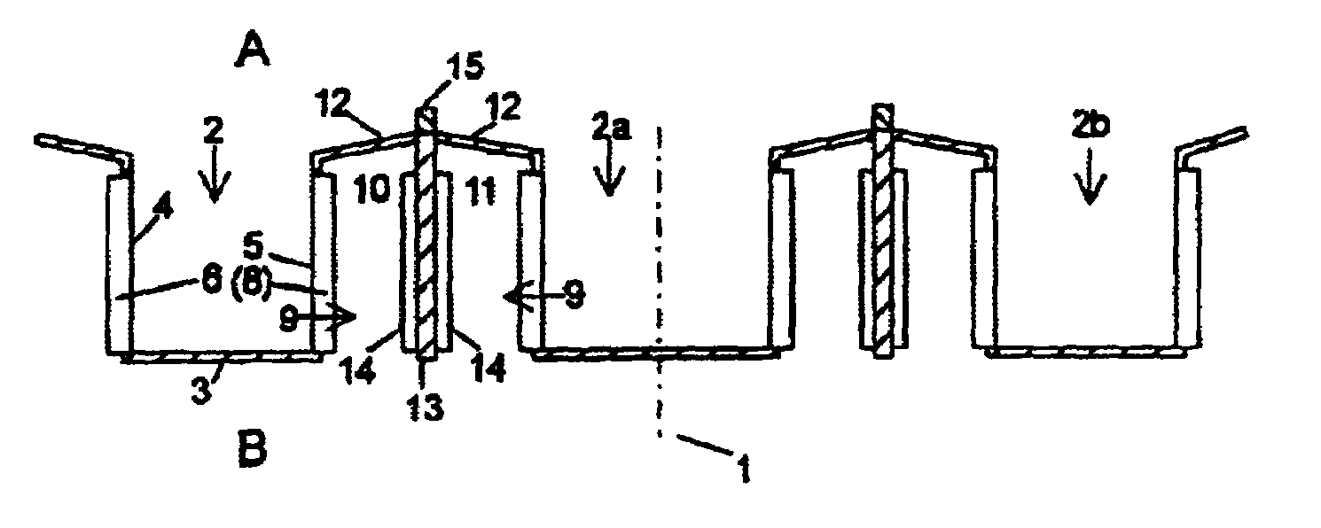
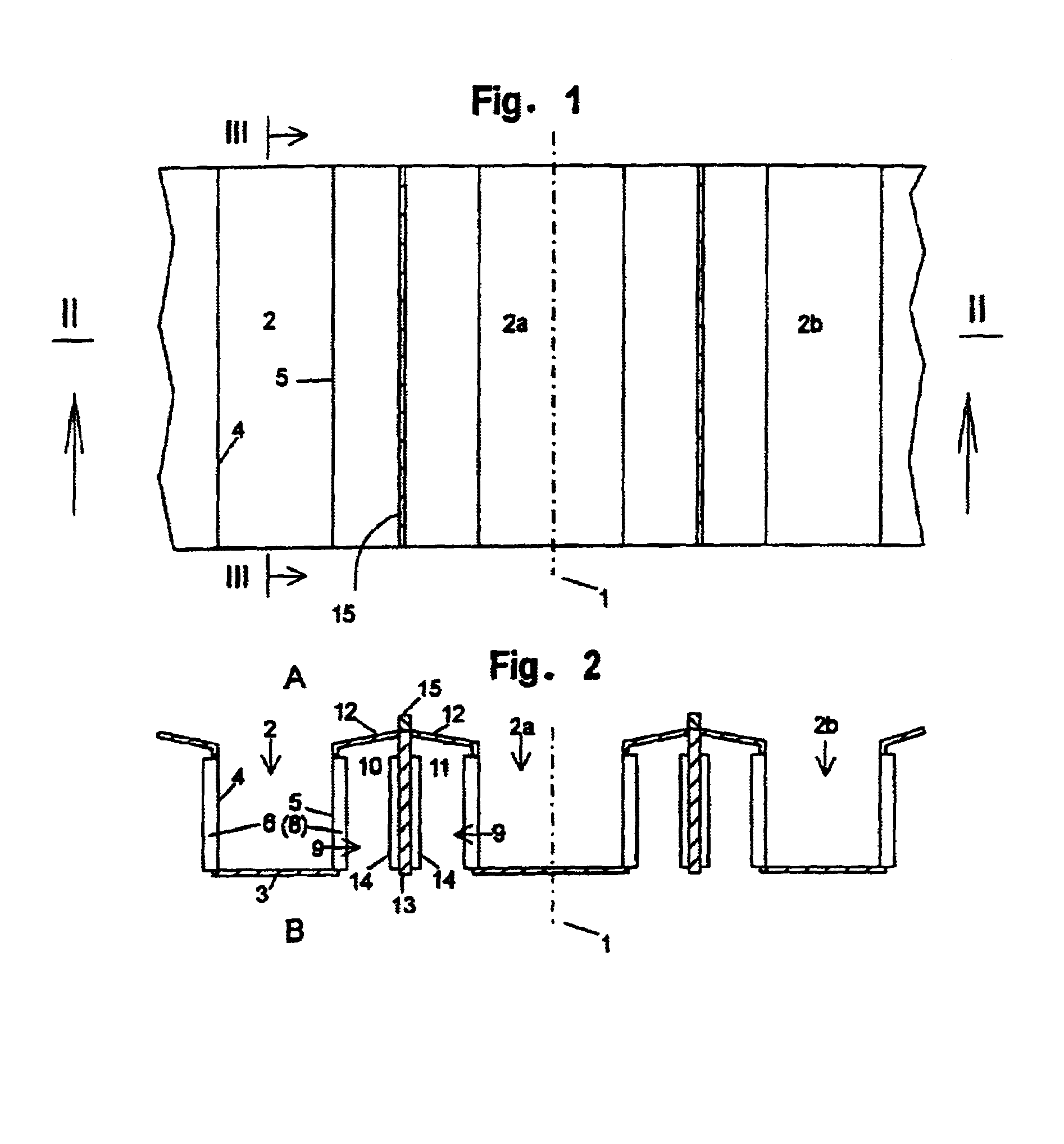
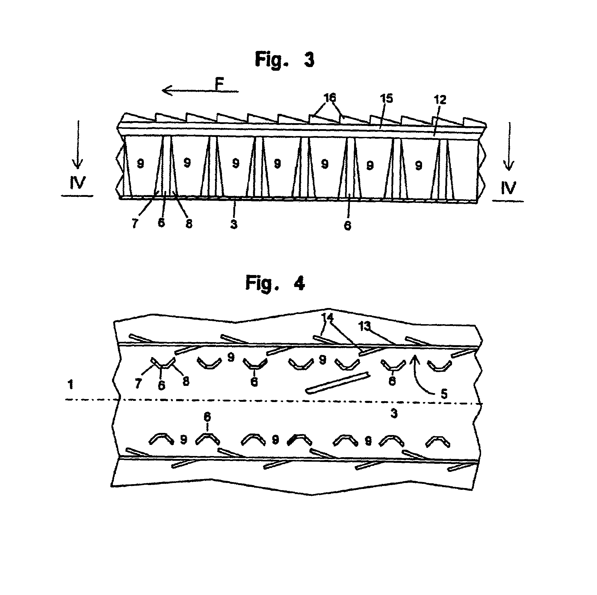
[0024]FIGS. 1 to 4 show only portions of a sieve according to the invention.

[0025]Within a thresher, the sieve according to the invention, formed as a cleaning sieve, represents a sieve. The sieve is loaded by, a not represented, upper sieve or a conveying bottom of an agricultural harvesting machine with a harvesting goods mixture of grains, chaff and small stalk parts.

[0026]The sieve includes several channels 2, 2a, 2b extending parallel to each other and to a longitudinal axis 1. Only three channels are represented. As each channel corresponds design-wise essentially to the others, only one channel is described in more detail, namely channel 2 and the connection area towards channel 2a.

[0027]The channel 2 has a bottom 3, formed continuously smooth, and two flanks, a first flank 4 and a second flank 5, transversely...


PUM


Abstract

A sieve for a thresher, especially a combine-harvester, for the separation of grain-like field fruits from stalk-like and chaff-like components has channels (2, 2a, 2b) extending parallel to a longitudinal axis (1). The channels (2, 2a, 2b) are open to a first side A, from which they are loaded. The channels (2, 2a, 2b) are delimited by a bottom 3 and laterally following flanks (4, 5) which include openings (9). Air guide following channels (10, 11) are open to a second side B, which face away from the first side A. The two air guide channels (10, 11) are arranged in a direction transverse to the longitudinal axis (1) and are separated by a continuous separation wall (13). The separation wall (13) extends between two neighbouring channels (2, 2a) which extend parallel to the longitudinal axis (1). In these separated air guide channels (10, 11), respectively, the openings (9) of only one of the two channels (2, 2a) separated by the air guide channels (10, 11) are open.

Description

CROSS-REFERENCE TO RELATED APPLICATIONS[0001]This application claims priority to German Patent Application No. 10352321.9 filed Nov. 6, 2003, which application is herein expressly incorporated by reference.FIELD OF THE INVENTION[0002]The invention relates to a sieve for a thresher, especially a combine-harvester, to separate grain-like field fruits from stalk-like or chaff-like constituents.BACKGROUND OF THE INVENTION[0003]Modern threshers, especially large combine-harvesters, have very aggressive threshing equipment, which not only disengage the grains from the stalks but also very heavily comminute the stalks. Thus, a large number of short stalk portions or chaff-like constituents are produced, which heavily load the sieve. This has the disadvantage, that the short stalks can align in the conveying direction and provide no sufficient resistance for the air blower to transport them away.[0004]DE 44 24 383 C2 (=U.S. Pat. No. 5,588,912) describes a cleaning sieve having parallel to t...

Claims


Application Information

Patent Timeline
Patent Type & Authority Patents(United States)
IPC IPC(8): A01F12/32B07B1/00A01F12/44
CPCA01F12/446A01F12/36
Inventor SCHUMACHER, GUSTAVSCHUMACHER, FRIEDRICH-WILHELM
Owner GUSTAV SCHUMACHER
Learn More