Write head design with improved bump to control write saturation

a writing head and writing technology, applied in the direction of head windings, head windings with metal sheet cores, magnetic recording, etc., can solve the problems of reducing write efficiency and certain limitations of bumping, and achieve the effect of better throat control

Inactive Publication Date: 2006-09-19
HITACHI GLOBAL STORAGE TECH NETHERLANDS BV
View PDF17 Cites 12 Cited by
  • Summary
  • Abstract
  • Description
  • Claims
  • Application Information

AI Technical Summary

Benefits of technology

[0011]According to one embodiment of the present invention, a head has an air bearing surface (ABS) and a first pole tip. A second pole tip is spaced apart from and facing the upper end of the first pole tip across a write gap. A bump extends into a portion of the upper end of the first pole tip and a portion of the bottom surface of the second pole tip, the bump being positioned away from the ABS. The bump defines a throat height of the first and second pole tips with substantially less topography than was heretofore known. This reduced topography makes pole process more robust for P2 track width control. Also, sufficient separation is created between the first and second pole tips in the bump region to ensure sufficient magnetic separation in a short effective throat height.
[0013]The bump is constructed of a nonmagnetic material such as alumina, a nonmagnetic metal (electrically conductive or nonconductive), and / or cured photoresist. Preferably, the bump is formed using a dry process such as by vacuum deposition. Using a dry process of bump formation provides an advantage in position control, resulting in better throat control, which is critical for short throat height writers.

Problems solved by technology

However, there are certain limitations on creating the bump 136.
If the bump 136 is too short, leakage across the write gap occurs, which in turn reduces write efficiency.

Method used


Image

  • Write head design with improved bump to control write saturation
  • Write head design with improved bump to control write saturation
  • Write head design with improved bump to control write saturation

Examples


Embodiment Construction

[0030]The following description is the best embodiment presently contemplated for carrying out the present invention. This description is made for the purpose of illustrating the general principles of the present invention and is not meant to limit the inventive concepts claimed herein.

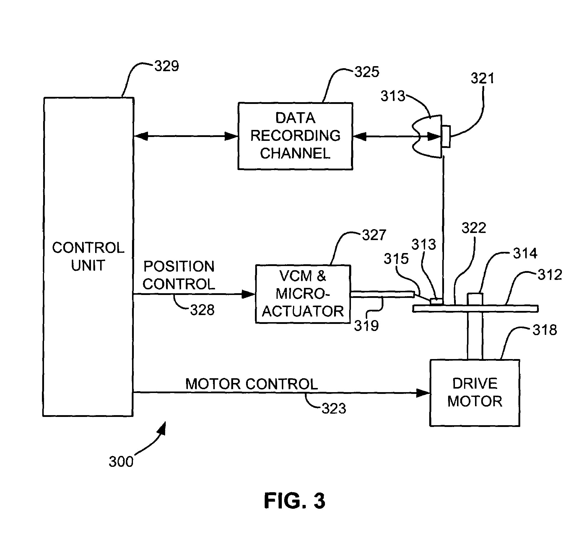
[0031]Referring now to FIG. 3, there is shown a disk drive 300 embodying the present invention. As shown in FIG. 3, at least one rotatable magnetic disk 312 is supported on a spindle 314 and rotated by a disk drive motor 318. The magnetic recording on each disk is in the form of an annular pattern of data tracks (not shown) on the disk 312.

[0032]At least one slider 313 is positioned near the disk 312, each slider 313 supporting one or more magnetic read / write heads 321. As the disks rotate, slider 313 is moved radially in and out over disk surface 322 so that heads 321 may access different tracks of the disk where desired data are recorded. Each slider 313 is attached to an actuator arm 319 by way of ...


PUM

PropertyMeasurementUnit
heightaaaaaaaaaa
circular shapeaaaaaaaaaa
oval shapeaaaaaaaaaa

Abstract

A magnetic head having an air bearing surface (ABS) and a first pole tip. A second pole tip is spaced apart from and facing the upper end of the first pole tip across a write gap. A bump extends into a portion of the upper end of the first pole tip and a portion of the bottom end of the second pole tip, the bump being positioned away from the ABS. The bump defines a throat height of the first and second pole tips.

Description

FIELD OF THE INVENTION[0001]The present invention relates to write heads, and more particularly, this invention relates to a write head having an integrated bump that defines pole tip throat heights for controlling write saturation.BACKGROUND OF THE INVENTION[0002]A typical magnetic disk drive includes a rotating magnetic disk, a slider that has read and write heads, a suspension arm above the rotating disk and an actuator arm that swings the suspension arm to place the read and write heads over selected circular tracks on the rotating disk. The suspension arm biases the slider into contact with the surface of the disk when the disk is not rotating but, when the disk rotates, air is swirled by the rotating disk adjacent an air bearing surface (ABS) of the slider causing the slider to ride on an air bearing a slight distance from the surface of the rotating disk. When the slider rides on the air bearing the write and read heads are employed for writing magnetic transitions to and rea...

Claims


Application Information

Patent Timeline
Patent Type & Authority Patents(United States)
IPC IPC(8): G11B5/147G11B5/127G11B5/60
CPCG11B5/127G11B5/60G11B5/147
Inventor LEE, EDWARD HIN PONGPENTEK, KATALINSHEN, YONGZHANG, SUE SIYANG
Owner HITACHI GLOBAL STORAGE TECH NETHERLANDS BV
Why Eureka
Try Eureka