Pressure distribution measuring system

a technology of pressure distribution and measuring system, which is applied in the field of pressure distribution measuring system, can solve the problems of affecting the measuring accuracy, degrading the accuracy of affecting the measurement accuracy, and achieve the effect of accurately measuring a pressure distribution on the surfa

Active Publication Date: 2006-10-03
HONDA MOTOR CO LTD
View PDF7 Cites 12 Cited by
  • Summary
  • Abstract
  • Description
  • Claims
  • Application Information

AI Technical Summary

Benefits of technology

[0010]The present invention has been accomplished with the above circumstance in view. It is an object of the present invention to provide a pressure distribution measuring system capable of accurately measuring a pressure distribution on a surface of an object.
[0016]With the arrangement of the present invention, the object is provided with the integrally formed measuring segment. A plurality of thin membranes are formed on a surface of the measuring segment at predetermined intervals in the fluid flow direction. A distortion gauge is fixed to a back face of each of the plurality of thin membranes to output an electric signal which is converted by a pressure conversion means into pressure, thereby measuring a pressure distribution in the flow direction. Therefore, it is possible to prevent the generation of a step, a gap and the like in the surface of the measuring segment which affect the fluid flow, thereby improving accuracy in measuring a pressure distribution. In addition, because the pressure detecting bores are not required, the measuring accuracy cannot be lowered due to stain and dust which adhere to the pressure detecting bores. Further, passages connecting the pressure detecting bores to pressure sensors are not required. Thus, it is possible to prevent a pressure loss, a pressure leakage and a measurement time-lag which are caused by the passages, thereby improving accuracy in measuring a pressure distribution. Furthermore, the pressure measurement range can be easily adjusted by merely changing the thickness of the thin membranes.
[0017]With the arrangement of the present invention, the measuring segment is constructed as a high-rigidity frame by connecting together the longitudinal frames extending in the fluid flow direction and the lateral frames extending in a direction orthogonal to the longitudinal frames, while outer peripheries of the thin membranes are connected to the longitudinal frames and the lateral frames. Therefore, the deformation amount of the thin membrane due to pressure acting on the surface of the object can be stabilized, to thereby improve accuracy in measuring a pressure distribution.
[0018]With the arrangement of the present invention, the measuring segment is integrally molded by the optical molding method. Thus, the measuring segment having a complicated shape can be formed with a high accuracy and a low cost.

Problems solved by technology

If the plurality of pressure detecting bores opening in the wing surface are formed along the cord line as disclosed in Japanese Patent Application Laid-open No. 2002-206987, the following problems occur: turbulence of airflow caused by the upstream pressure detecting bore affects the downstream pressure detecting bore, thereby degrading the accuracy in measuring a pressure distribution, and also pressure loss and pressure leakage caused by the passages formed within the wing model for connecting the pressure detecting bores to the pressure sensors affect the measuring accuracy; time lag is generated in the measurement, because the passages are long; a measurable pressure range is narrow; the measuring accuracy degrades due to stain and dust adhering to the pressure detecting bores; and the measurement in water (in the case of marine vessels) is impossible.
PCT / DE00 / 01468, the wing shell having the piezo-foil bonded to its inner surface is fixed to cover the opening formed in the wing surface, leading to a problem that a step or a gap is generated along an outer periphery of the wing shell to cause turbulence of airflow.
Further, the piezo-foil has a characteristic of outputting a signal upon deformation but not outputting the signal in a steady state in which deformation amount is constant, leading to a difficulty in measuring a pressure distribution on the wing surface in the steady state.

Method used


Image

  • Pressure distribution measuring system
  • Pressure distribution measuring system
  • Pressure distribution measuring system

Examples


Embodiment Construction

[0030]The mode for carrying out the present invention will now be described by way of embodiments of the present invention with reference to the accompanying drawings.

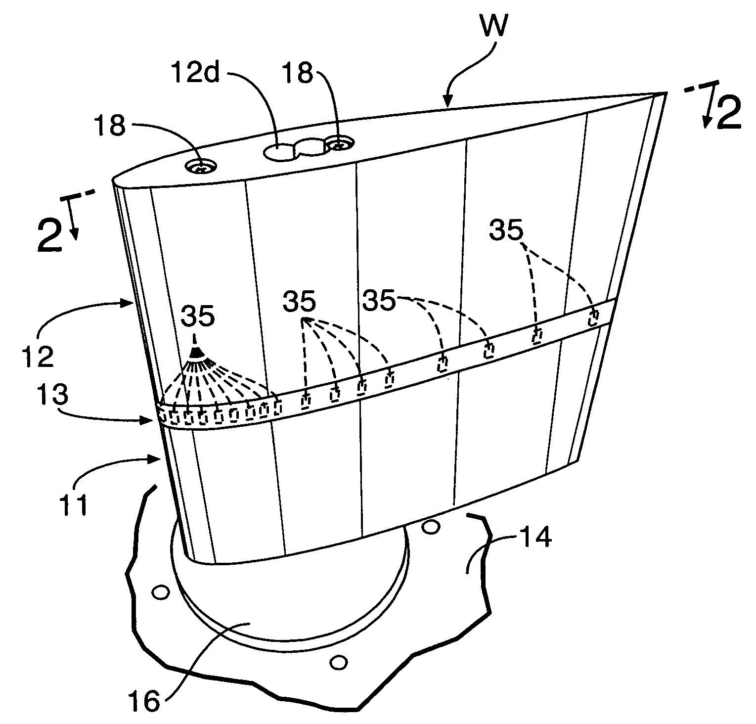
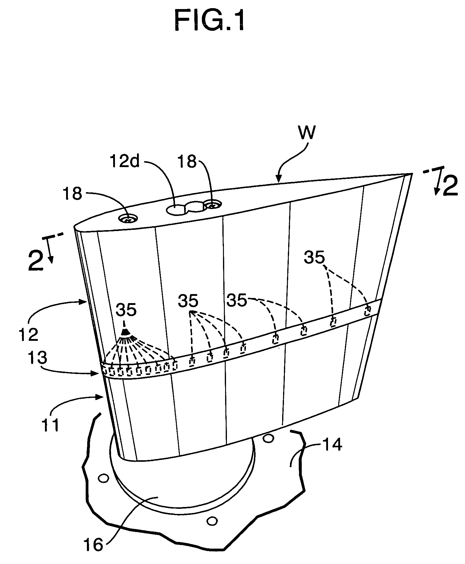
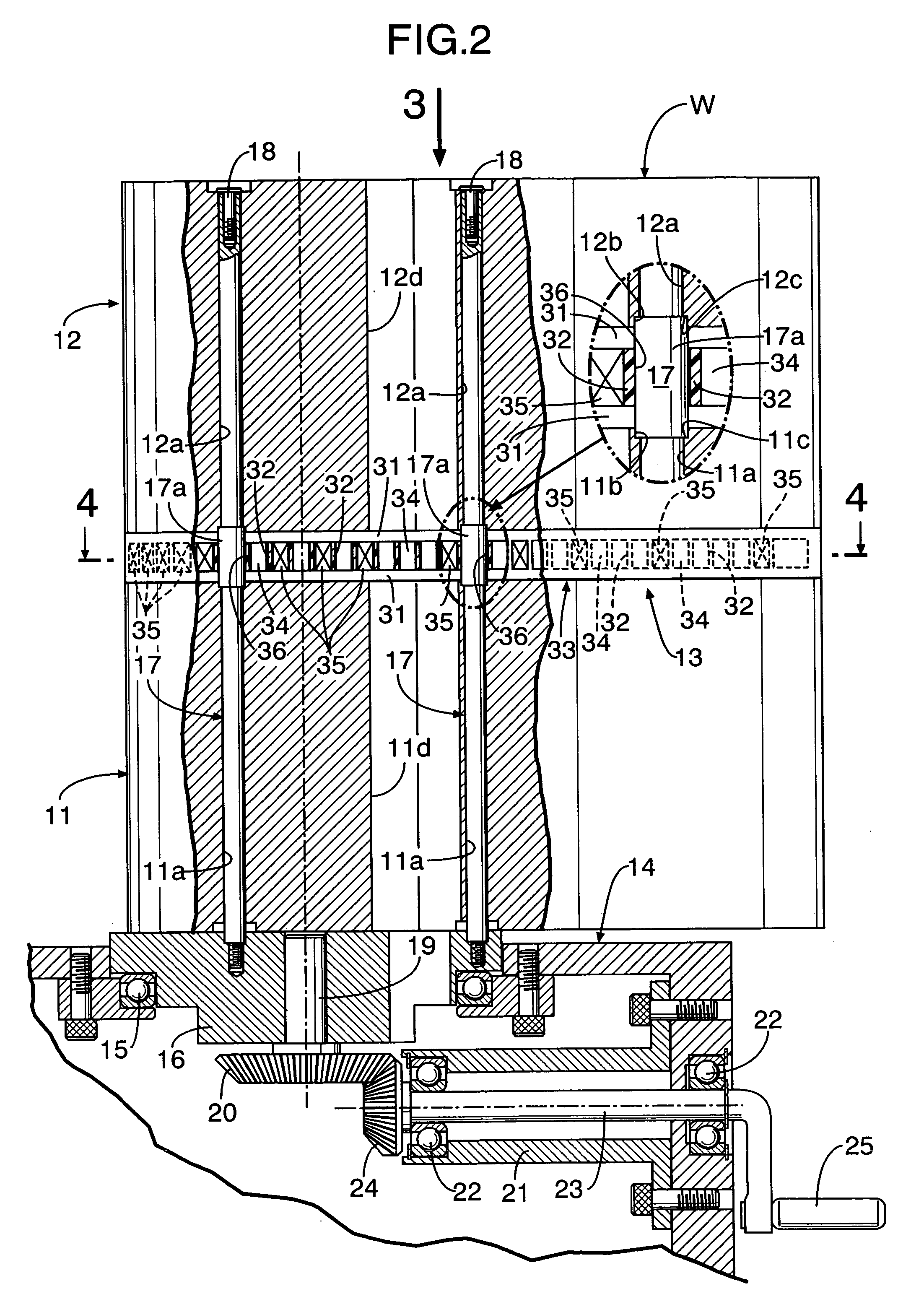
[0031]FIGS. 1 to 3 show a wing model W used for measuring a pressure distribution on a surface of a wing of an airplane in a wind tunnel test. The wing model W includes: first and second wing bodies 11 and 12 each made of a metal and separated vertically from each other; and a measuring segment 13 made of a synthetic resin and interposed between the first and second wing bodies 11 and 12. Each of the first and second wing bodies 11 and 12 and the measuring segment 13 has a certain blade airfoil in a span direction.

[0032]The first wing body 11, the measuring segment 13 and the second wing body 12 are superposed on an upper surface of a turn table 16 rotatably carried on a base member 14 with a ball bearing 15 interposed therebetween, and are fixed by two fixing rods 17, 17 spaced apart from each other in a cord directio...


PUM

PropertyMeasurementUnit
pressureaaaaaaaaaa
pressure distributionaaaaaaaaaa
widthaaaaaaaaaa

Abstract

A measuring segment is integrally formed in a wing model. A plurality of thin membranes are formed on a surface of the measuring segment at predetermined intervals in a cord direction with a distortion gauge fixed to a back face of each of the plurality of thin membranes to output an electric signal upon distortion. The electric signals are converted by a pressure conversion means into pressures, thereby measuring a pressure distribution in an airflow direction. It is possible to prevent the generation of a step or a gap which affects an airflow along the surface of the measuring segment, thereby improving accuracy. The measuring segment is integrally molded by an optical molding method to form a complicated shape with a high accuracy and a low cost. Further, a plurality of the measuring segments may be disposed at intervals in a span direction for measuring pressure distributions.

Description

CROSS-REFERENCE TO RELATED APPLICATIONS[0001]The present application is related to Japanese Patent Application No. 2004-30457 filed on Feb. 6, 2004 the entire contents of which are hereby incorporated by reference.BACKGROUND OF THE INVENTION[0002]1. Field of the Invention[0003]The present invention relates to a pressure distribution measuring system for measuring a pressure distribution along a predetermined fluid flow direction on a surface of an object moving relative to a fluid.[0004]2. Description of Background Art[0005]A pressure distribution measuring system for measuring a pressure distribution along a predetermined fluid flow direction on a surface of an object moving relative to a fluid is used in many fields such as aircraft, marine vessels, automobiles, buildings and bridge beams.[0006]For example, in the field of aviation, Japanese Patent Application Laid-open No. 2002-206987 discloses a wing model used for measuring a pressure distribution along a cord line on a wing su...

Claims


Application Information

Patent Timeline
Patent Type & Authority Patents(United States)
IPC IPC(8): A63B53/00G01L15/00G01M9/06
CPCG01L15/00G01M9/06G01M9/065
Inventor OMOTANI, HIDEO
Owner HONDA MOTOR CO LTD
Why Eureka
Try Eureka