Interference measuring apparatus and interference measuring method

a measuring apparatus and interference technology, applied in the direction of interferometers, measurement devices, instruments, etc., can solve the problems of increasing measurement errors and difficulty in accurate measurement, and achieve the effect of accurately measuring a surfa

Inactive Publication Date: 2014-06-12
CANON KK
View PDF5 Cites 2 Cited by
  • Summary
  • Abstract
  • Description
  • Claims
  • Application Information

AI Technical Summary

Benefits of technology

[0009]The present invention has been made in view of the above circumstances and has an object to provide an interference measuring apparatus that is advantageous for accurately measuring a surface to be inspected even when the surface to be inspected is a rough surface.
[0011]According to the present invention, an interference measuring apparatus that is advantageous for accurately measuring a surface to be inspected even when the surface to be inspected is a rough surface may be provided.

Problems solved by technology

In such an interferometer using light of single wavelength, if a surface to be inspected has a certain roughness (surface roughness), a speckle pattern caused by the roughness of the surface has a random phase with a standard deviation greater than 2n, resulting in an increase in measurement error.
As described above, even when a multi-wavelength interferometer is used for rough surface measurement, it is difficult to perform an accurate measurement due to a decrease in the correlation between two wavelengths if a surface to be inspected is not significantly aligned with the focus position of an objective lens.

Method used


Image

  • Interference measuring apparatus and interference measuring method
  • Interference measuring apparatus and interference measuring method
  • Interference measuring apparatus and interference measuring method

Examples


first embodiment

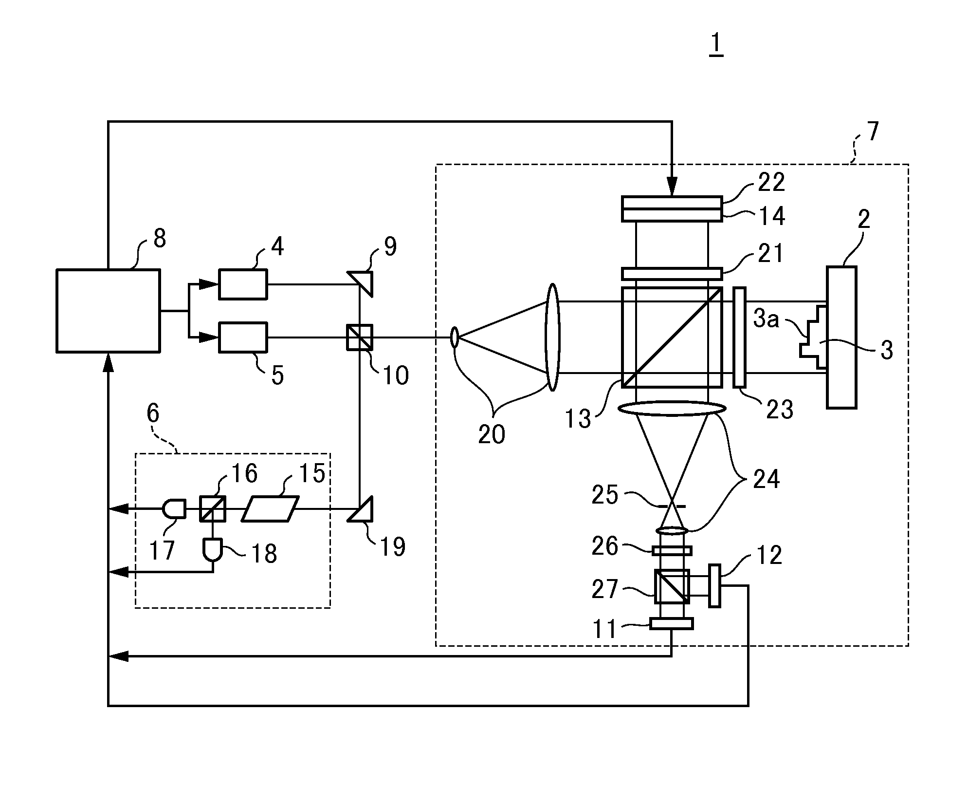
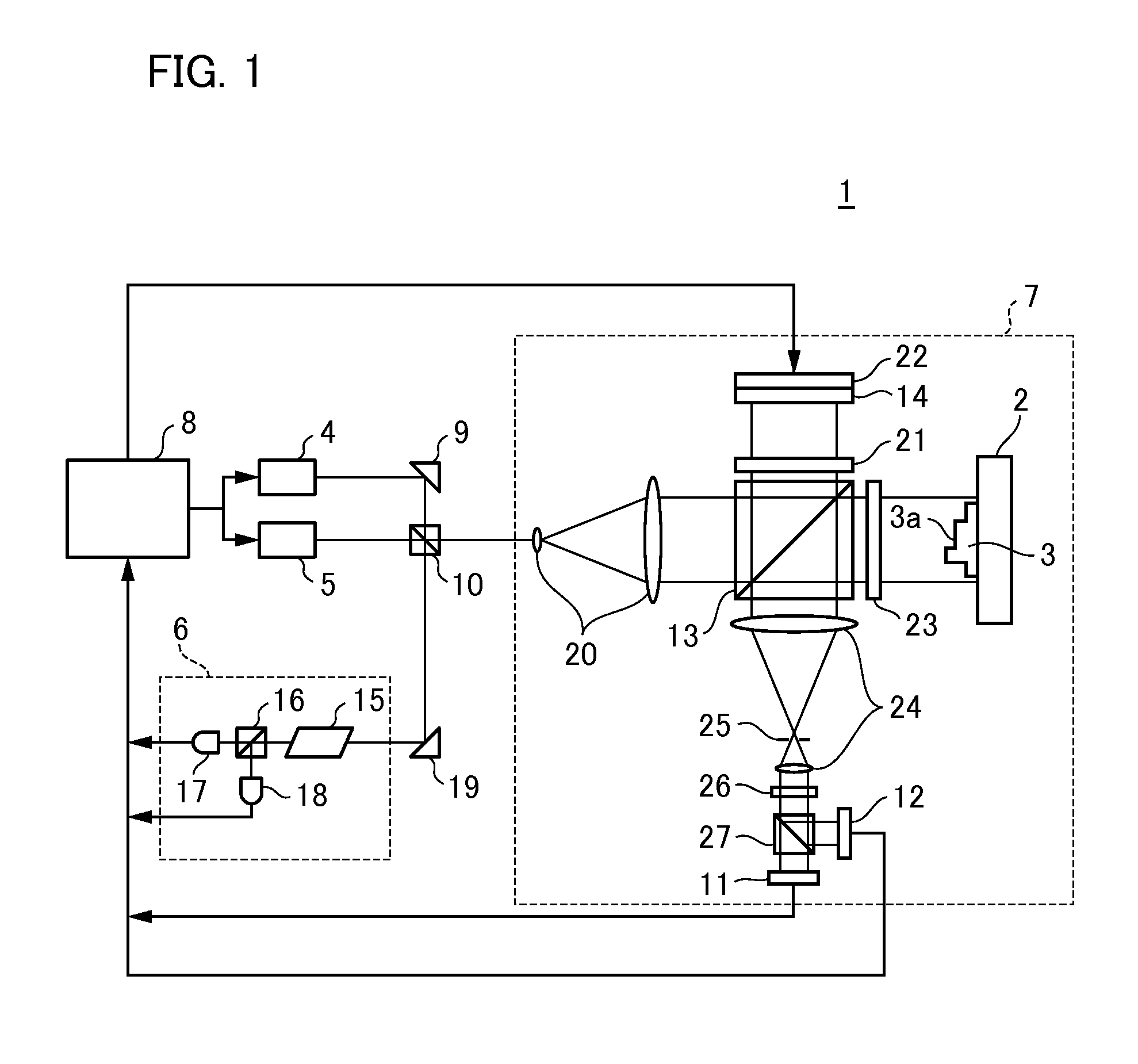
[0022]Firstly, a description will be given of an interference measuring apparatus according to a first embodiment of the present invention. FIG. 1 is a schematic diagram illustrating a configuration of an interference measuring apparatus 1 according to the present embodiment. The interference measuring apparatus 1 is a multi-wavelength interferometer that measures the shape (the distance among a plurality of points) of a surface to be inspected 3a of an object (object to be measured) 3 placed on a placing table 2 by using a plurality of (in the present embodiment, two as an example) light fluxes (light waves) whose wavelengths are different from each other. The interference measuring apparatus 1 firstly includes a first light source (first laser light source) 4 that emits first light (first laser) having a first fixed wavelength and a second light source (second laser light source) 5 that emits second light (second laser) having a second fixed wavelength different from the first fix...

second embodiment

[0038]Next, a description will be given of an interference measuring apparatus according to a second embodiment of the present invention. FIG. 4 is a schematic diagram illustrating a configuration of an interference measuring apparatus 30 according to the present embodiment. Although the interference measuring apparatus 1 of the first embodiment measures the shape of the surface to be inspected 3a all at once, a feature of the interference measuring apparatus 30 lies in the fact that single-point distance (length measurement distance) is calculated at high speed. In the interference measuring apparatus 30, a stage device (not shown) is disposed and the surface to be inspected 3a is movable in a planar direction (XY plane) while the object 3 is placed on the stage device, so that the shape of the surface to be inspected 3a can be measured as in the first embodiment. Furthermore, in the interference measuring apparatus 30, a galvano mirror instead of a stage device is disposed between...


PUM


Abstract

An interference measuring apparatus measuring a distance to a surface for inspection is provided. The interference measuring apparatus includes a light dividing unit that divides each of the plurality of light fluxes into light to be inspected and reference light; an objective lens that transmits light to be inspected; a photoelectric conversion element that receives interference light between the light to be inspected and the reference light for each of the plurality of light fluxes and output an interference signal obtained by converting the interference light into an electrical signal; and a calculation unit that calculates the distance to the surface to be inspected based on a phase obtained by subtracting a defocused wavefront from a phase component of a complex amplitude at the pupil position of the objective lens which transmitted light to be inspected for each of the plurality of light fluxes by using the interference signal.

Description

BACKGROUND OF THE INVENTION[0001]1. Field of the Invention[0002]The present invention relates to an interference measuring apparatus and an interference measuring method.[0003]2. Description of the Related Art[0004]Conventionally, interferometers (interference measuring apparatuses) using a light wave are known as apparatuses for measuring the shape of an object or the like with high accuracy. In such an interferometer using light of single wavelength, if a surface to be inspected has a certain roughness (surface roughness), a speckle pattern caused by the roughness of the surface has a random phase with a standard deviation greater than 2n, resulting in an increase in measurement error. Accordingly, there has been proposed a multi-wavelength interferometer for measuring a rough surface profile on an object to be inspected using a plurality of different wavelength lights. In an article entitled “Rough surface interferometry with a two-wavelength heterodyne speckle interferometer” by...

Claims


Application Information

Patent Timeline
Patent Type & Authority Applications(United States)
IPC IPC(8): G01B11/06
CPCG01B9/02007G01B9/02003G01B9/0207G01B11/303G01B9/02002G01B11/2441G01B9/02082G01B9/02075G01B9/02083G01B2290/50G01B2290/60G01B2290/45G01B11/0675
Inventor NISHIKAWA, YUYA
Owner CANON KK
Why Eureka
Try Eureka