Control of electroluminescent displays

a technology of electroluminescent display and control panel, which is applied in the direction of electric digital data processing, electric variable regulation, instruments, etc., to achieve the effect of preventing a significant voltage drop and smoothing out the load on the power supply

Inactive Publication Date: 2006-10-10
PELIKON
View PDF21 Cites 136 Cited by
  • Summary
  • Abstract
  • Description
  • Claims
  • Application Information

AI Technical Summary

Benefits of technology

[0028]The invention is applicable to controllers having a variety power supply systems. As noted above, it is normal practice to use a flyback converter to provide a comparatively high voltage from a low voltage input. Conventionally, the output from the flyback converter feeds into a large r

Problems solved by technology

However, in the case of displays having many segments this may not be practicable and so preferably

Method used


Image

  • Control of electroluminescent displays
  • Control of electroluminescent displays
  • Control of electroluminescent displays

Examples


Embodiment Construction

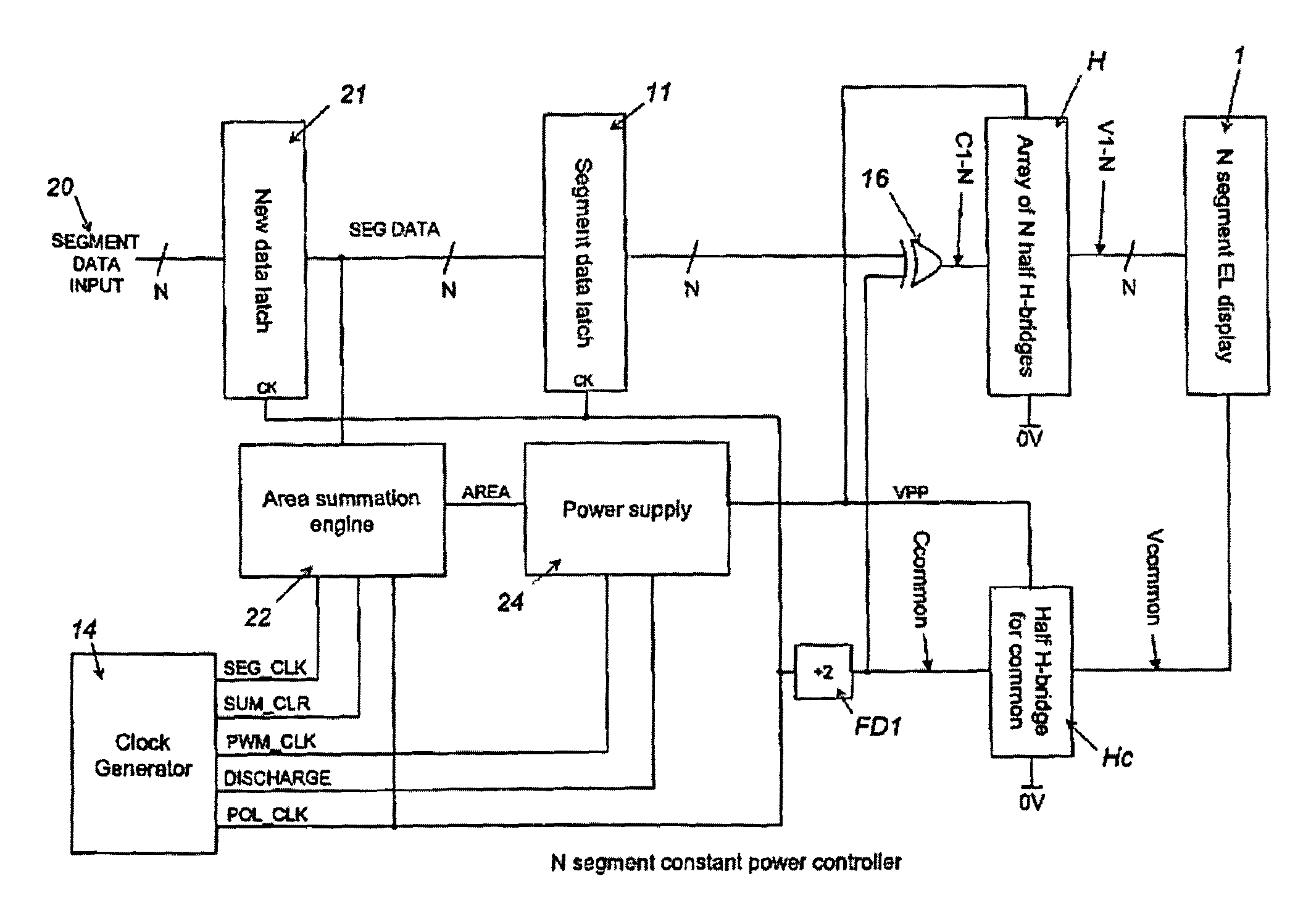
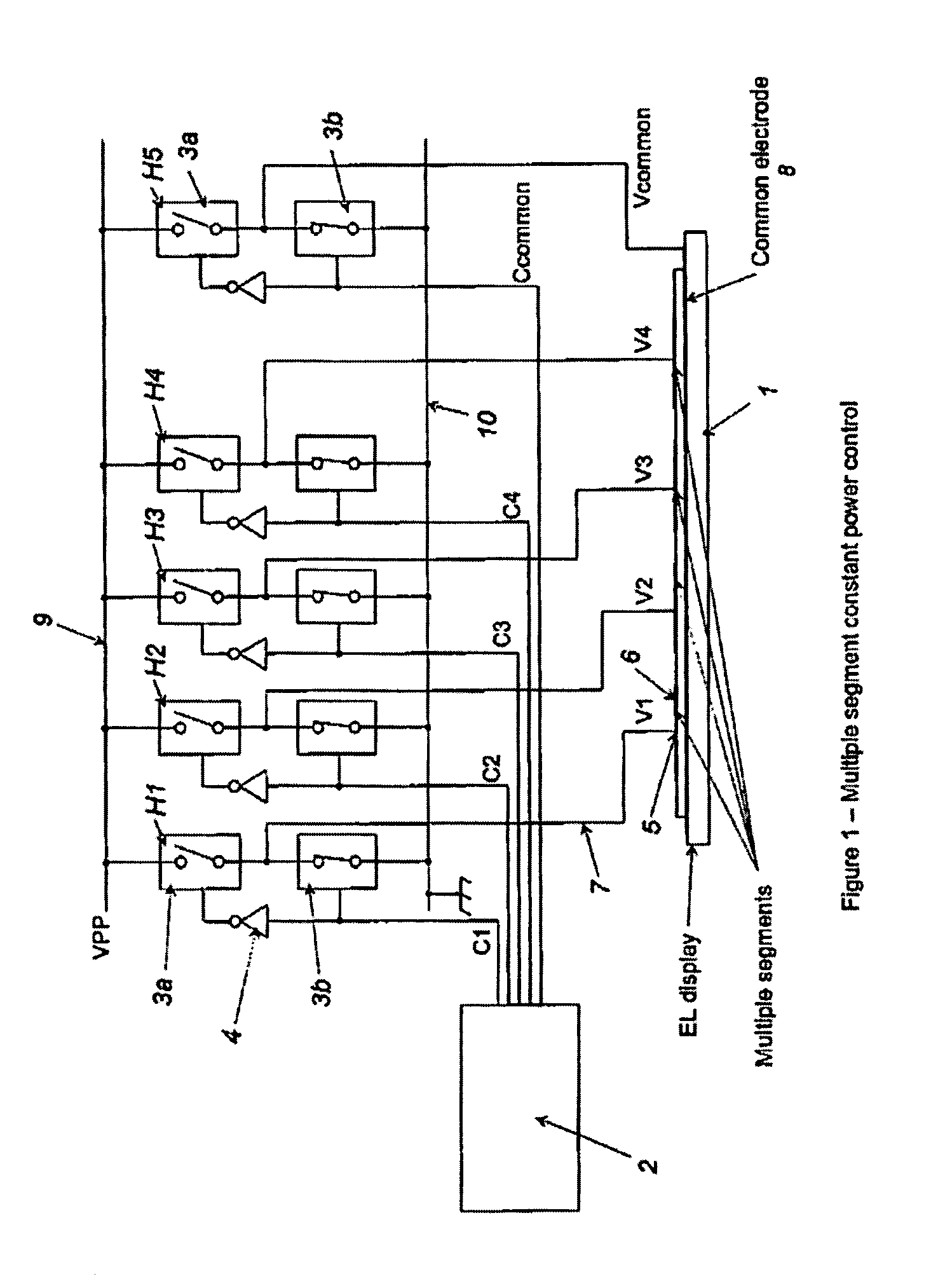
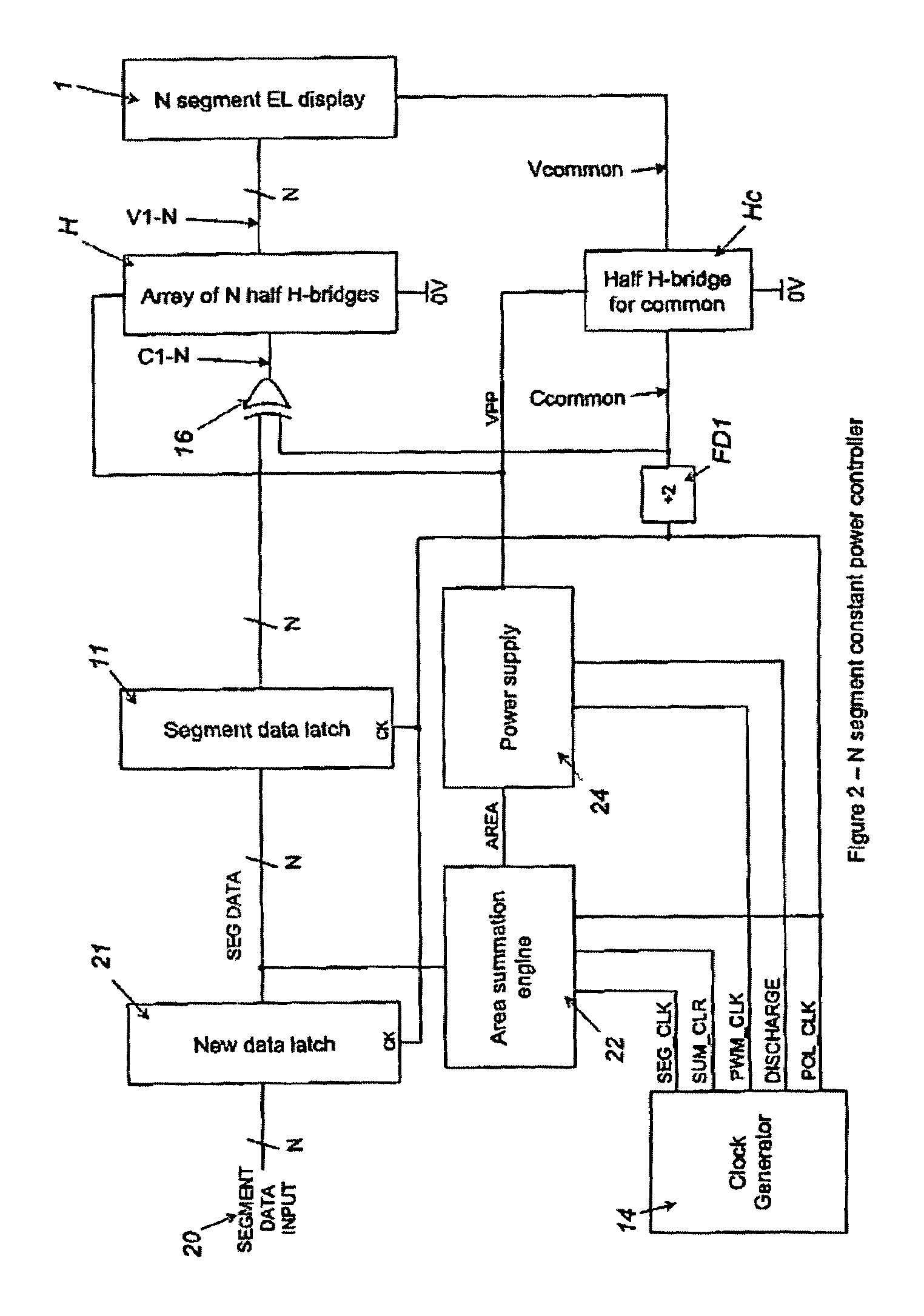
[0040]FIG. 1 shows a controller having the combination of output drivers required for a four-segment display 1. Control unit 2 is connected to five half H-bridges H1–H5 by conductors carrying control signals C1–C4 and Ccommon. Each half H-bridge comprises a pair of switches 3a, 3b in the form of MOSFET transistors and an inverter 4. The transistors are controlled by control signals C1–C4, the arrangement being such that when one switch of a pair is open, the other is closed.

[0041]The centre of each of half H-bridges H1–H4 is connected to the drive electrode 5 of one segment 6 of the display 1 via a conductor 7. The centre of half H-bridge H5 is connected to common electrode 8. The common electrode is made of a transparent conductive material and is connected to each segment in the known manner.

[0042]In addition, the half H-bridges are connected to a high-voltage supply 9 and to ground 10.

[0043]Control signals C1–C4 and Ccommon control the states of their respective half H-bridges H1...


PUM


Abstract

A controller for use with a multi-segment electroluminescent display 1. Control signals C1–CN control a plurality of half H-bridges H and Hc, the terminals of the half H-bridges being connected respectively to ground and to a high voltage DC supply 9. One of said half H-bridges provides a common output Vcommon and the remaining H-bridges provide drive voltages V1–VN for the segments of the display. The H bridges are driven by an oscillator 14 so that an AC voltage is selectively applied to the segments of the display. A power supply 24 provides a predetermined amount of power per unit area of the display. This is controlled by an area summation engine 22 having a segment data input, a segment counter and a memory containing area data corresponding to the segment(s) of the display. Based on the input from the segment data input, the area(s) of the segment(s) that are to be lit are obtained from the memory and summed to provide the total area to be lit. This is fed to the power supply 24, which then feeds the correct amount of power to display 1 via the half H-bridges.

Description

TECHNICAL FIELD[0001]The present invention relates to electroluminescent displays and their controllers and, in particular, to the control of the power supplied by such controllers.BACKGROUND OF THE INVENTION[0002]Electroluminescent displays have selectively illuminable regions for displaying information. Such displays have the advantage over competing technologies that they can be large, flexible and are relatively inexpensive.[0003]Although electroluminescent lamps were known in the 1950's, these had a short lifetime and it was not until the 1980's that a flexible electroluminescent device was developed. However, this was used as an LCD backlight and only recently have practical electroluminescent displays become available.[0004]Electroluminescent displays generally comprise a layer of phosphor material, such as a doped zinc sulphide powder, between two electrodes. It is usual for at least one electrode to be composed of a transparent material, such as indium tin oxide (ITO), prov...

Claims


Application Information

Patent Timeline
IPC IPC(8): G09G3/10G09G3/12H05B44/00
CPCG09G3/12H05B33/08G09G2330/021Y02B20/325Y02B20/30H05B44/00G09G3/30
Inventor FRYER, CHRISTOPHER JAMES NEWTONROSS, STEFAN MICHAEL
Owner PELIKON
Why Eureka
Try Eureka