
Grain moisture sensor
a technology of grain moisture sensor and sensor, which is applied in the direction of measuring devices, fertiliser distributors, instruments, etc., can solve the problems of increasing the difficulty of manufacturing and maintenance of this device, the difficulty of determining the exact point at which the reading is taken, and the difficulty of acquiring the device for either manufacture or repair, so as to facilitate the detection of the desired zero point, reduce the complexity, and the effect of reducing the complexity
- Summary
- Abstract
- Description
- Claims
- Application Information
AI Technical Summary
Benefits of technology
Problems solved by technology
Method used
Image

Examples
Embodiment Construction
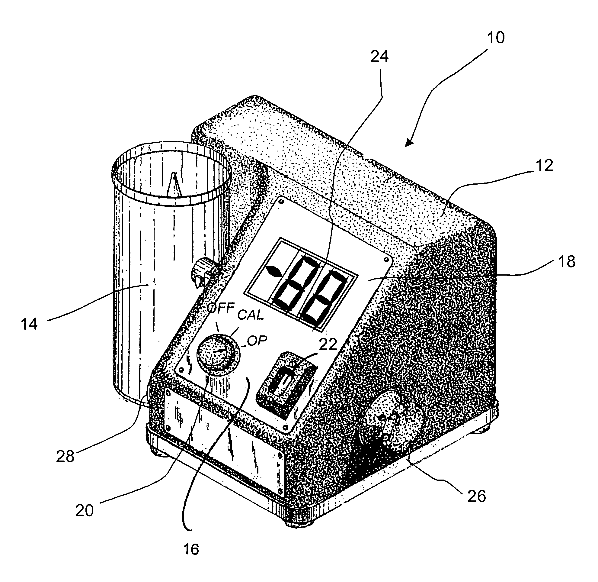
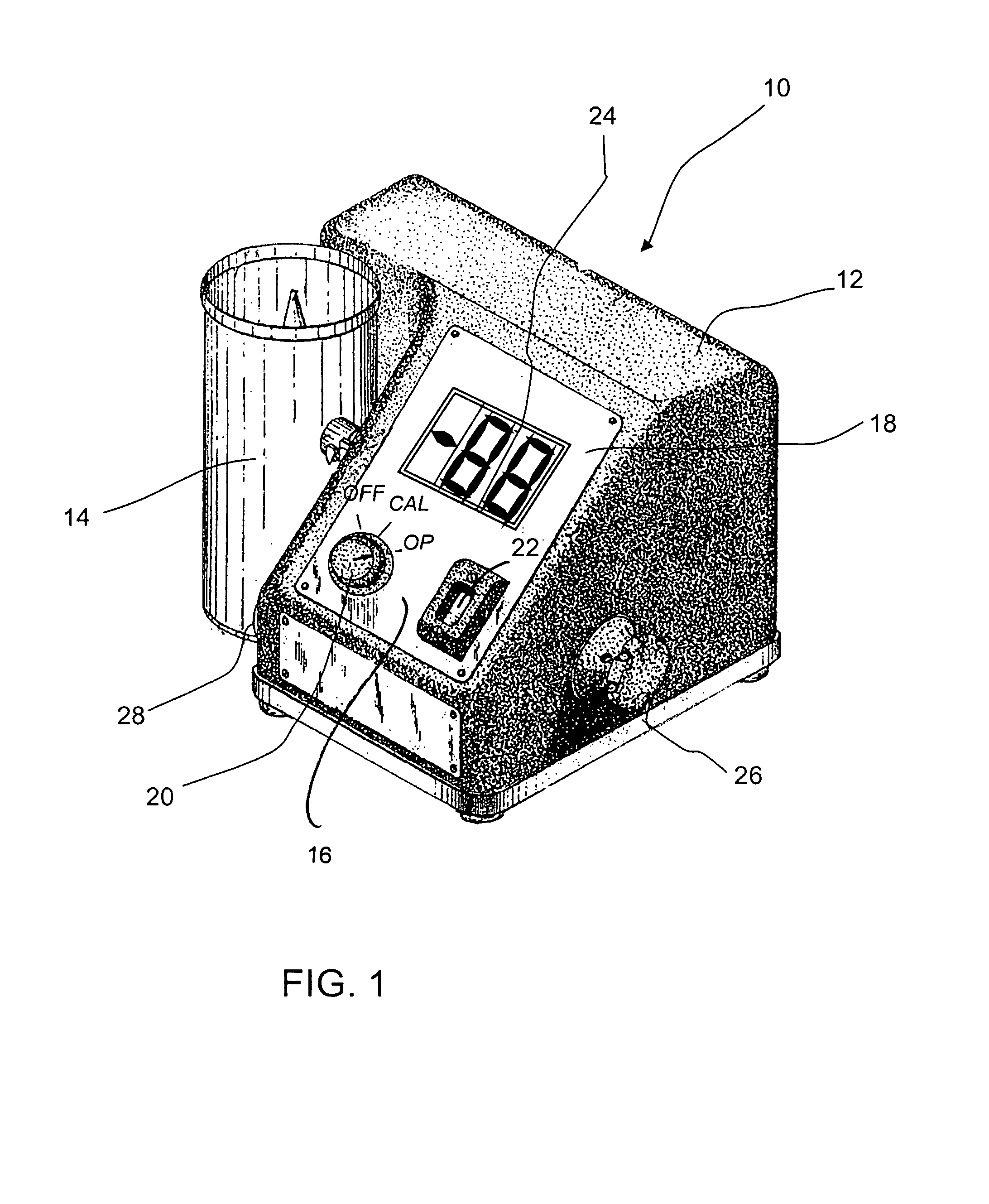
[0067]Referring to the accompanying drawings, there is illustrated a moisture tester 10 having a housing 12 and a test cell 14 for containing a sample of material to be tested. The configuration of the test cell and its mounting and connection to the housing are as described in CA 510,356. The front face 16 of the housing carries a panel 18 on which is mounted a multi-position switch 20 with “off”, “calibrate” and “operate” positions. The panel 18 also carries an indicator dial 22 for a standardized variable capacitor Cs (FIG. 3) and a two digit digital display 24. On one side of the housing is a knob 26 for adjusting the standardized variable capacitor with which the dial 22 is associated, while a trim knob 28 is mounted on the opposite side of the housing for adjusting a trimming capacitor. These components have equivalents in the device described in CA 510356, to which the reader is referred.
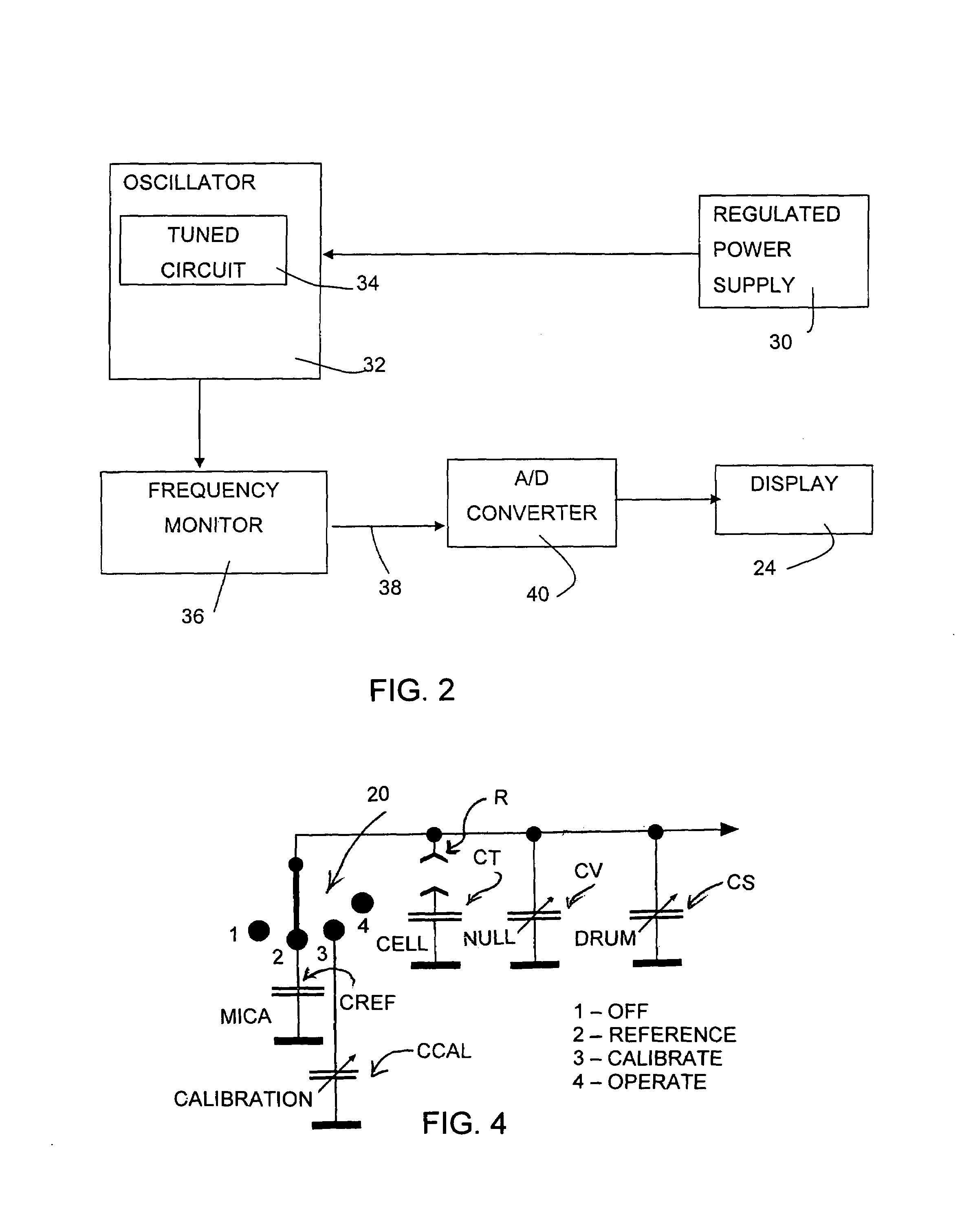
[0068]Turning to FIG. 2, the device according to the present invention has a regulated po...
PUM
 Abstract
Description
Claims
Application Information