Intraoral illumination device

a technology of illumination device and intraoral cavity, which is applied in the field of devices, can solve the problems of less maneuvering room available to the dental practitioner, complicated dental devices which incorporate a light source, and high retail price, and achieve the effect of clear interior view

Inactive Publication Date: 2006-12-26
CROHN ENTERPRISES
View PDF32 Cites 34 Cited by
  • Summary
  • Abstract
  • Description
  • Claims
  • Application Information

AI Technical Summary

Benefits of technology

[0024]It is an object of this invention to provide an inexpensively-manufactured, low-cost intraoral illuminating device.
[0025]It is yet another object of this invention to provide an intraoral illuminating device that can be easily positioned and secured in the mouth.
[0026]It is also an object of the invention to provide an intraoral illuminating device that does not take up the limited space in the mouth, permitting the dental practitioner to easily maneuver the dental instruments therein and perform the required procedures.
[0027]It is a further object of the invention to provide an intraoral illuminating device that is sufficiently low in cost so that it is disposable.
[0029]A first chamber and a second chamber are provided within the container. The chambers are connected to each other by a frangible wall. The first chamber contains a first chemical composition and the second chamber contains a second chemical composition. When the first and second chemical compositions are mixed together a chemiluminescent reaction takes place that produces light. When the frangible wall is fractured by flexing the container, it permits the first and second chemicals to mix within the container to create a chemiluminescent reaction that emits light through the portion of the container walls that are light transmitting to thereby illuminate the mouth and permit easy viewing of the interior of the mouth and for dental procedures to be easily performed therein without interference from the illuminating device.

Problems solved by technology

As shown in much of the prior art, dental devices which incorporate a light source are generally complicated, multi-element devices, each of which must each be manufactured separately, and then assembled by hand.
The labor required is likely to result in a retail price which makes it unlikely that such devices will be discarded after use with one patient.
Further, the design of many such devices requires a size which fills a significant portion of the mouth, and therefore leaves less maneuvering room available to the dental practitioner.

Method used


Image

  • Intraoral illumination device
  • Intraoral illumination device
  • Intraoral illumination device

Examples


Embodiment Construction

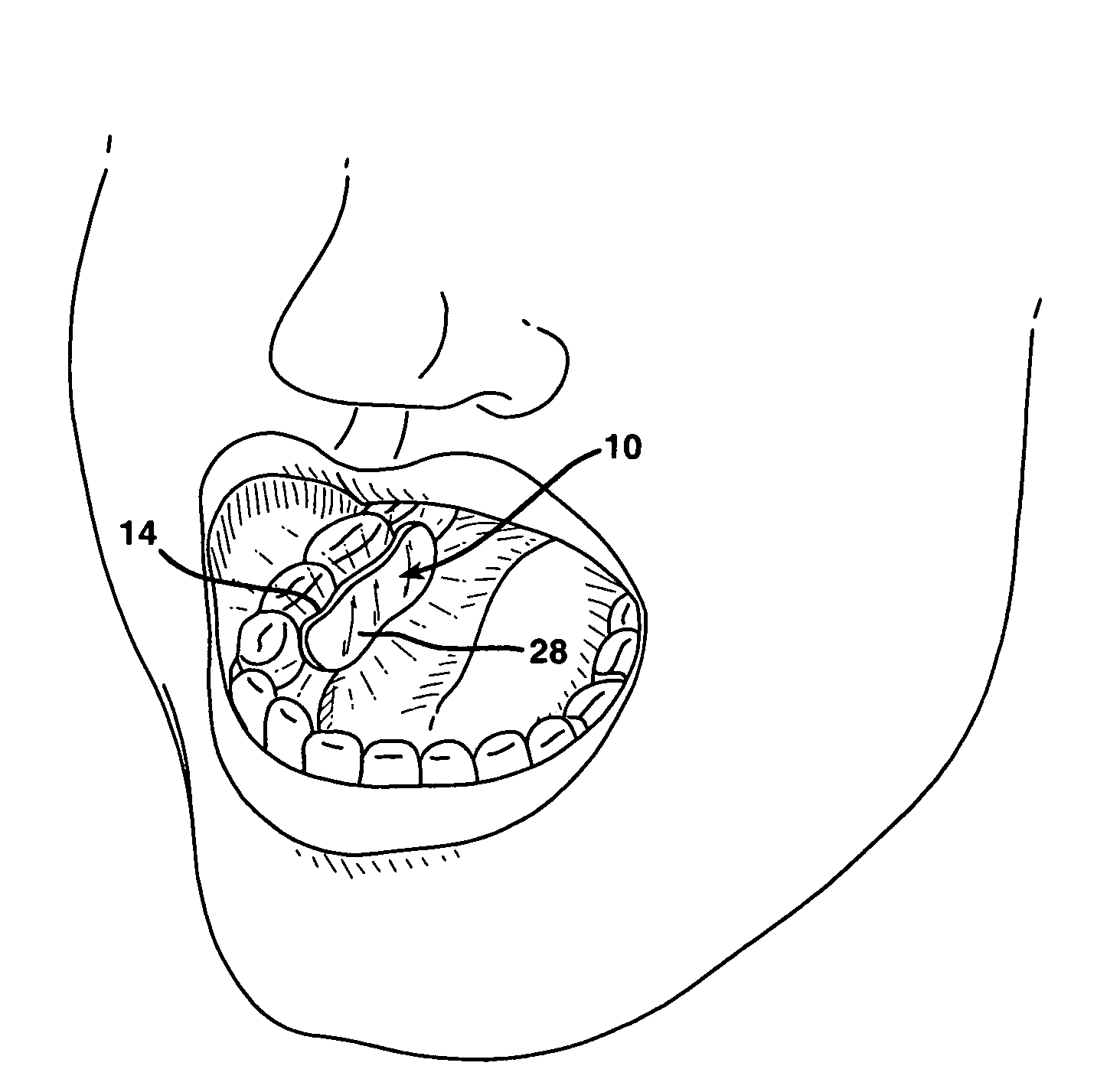
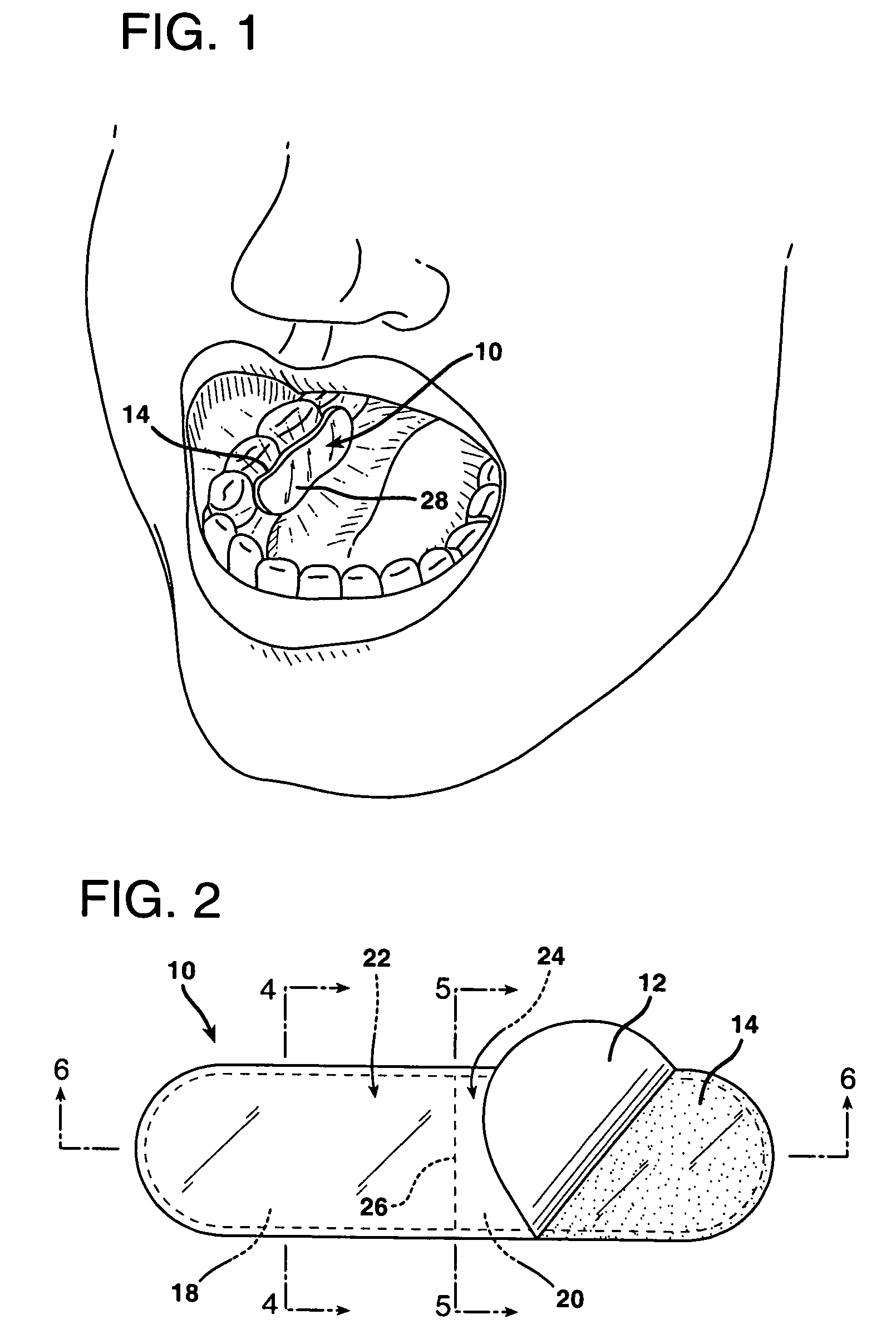
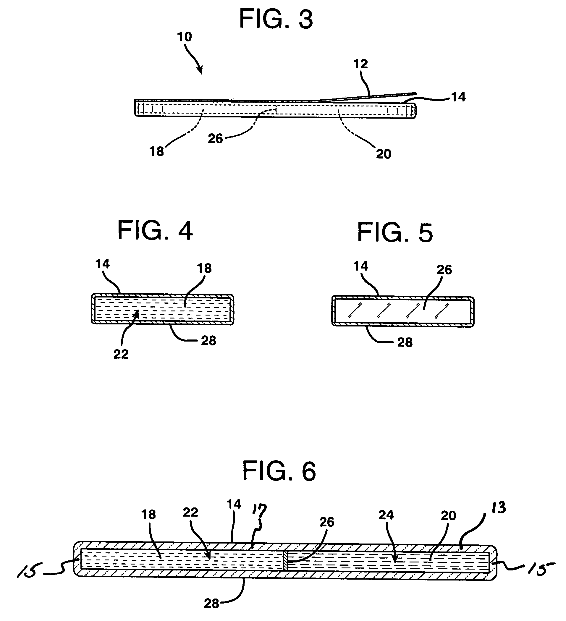
[0039]Referring to FIGS. 1–7, the intraoral illumination device 10 is used for illuminating the interior of the mouth of a dental patient. The device 10 comprises a flexible container, generally having container defining walls 13. In the embodiment depicted, the container walls comprise a top wall 17, a bottom wall 28 and sidewalls 15 connecting the top and bottom walls 17, 28. A portion of the walls 13 are light transmitting. For maximum light transmission and ease of manufacture of the device, it is preferred that the walls 17, 15 and 28 are all light transmitting.

[0040]It is preferred that appropriate polymers (plastics) be used for the walls 17, 15 and 28 both for ease of manufacture, cost and properties. The container is preferably made of a flexible transparent or translucent material, having sufficient rigidity to maintain its shape and sufficient flexibility to be fractured and shaped to conform to the surface, e.g., gum line, with which it comes into contact and is capable ...


PUM


Abstract

An intraoral illumination device for illuminating the interior of the mouth of a dental patient. The device comprises a flexible container having container defining walls, a portion of the walls being light transmitting. The device is sized for insertion into the mouth and placement against an interior surface of the mouth, e.g., the gum. A pressure-sensitive adhesive layer covers a portion of the walls for adhesively mounting the device to the interior surface of the mouth. A first chamber and a second chamber are within the container. The chambers are connected to each other by a frangible wall. Each of the chambers contain a chemical composition that when mixed together create a chemiluminescent reaction that produces light. When the frangible wall is fractured by flexing the container, it permits the compositions to mix within the container to create a chemiluminescent reaction that emits light through the container walls to illuminate the mouth, permitting dental procedures to be easily performed.

Description

BACKGROUND OF THE INVENTION[0001]1. Field of the Invention[0002]This invention relates to the field of devices for illuminating the interior of the mouth to permit dental procedures to be easily performed.[0003]2. Description of the Related Art[0004]The broad concept of lighting the interior of the mouth for dental purposes is well known. In widespread use in the dental profession are overhead lights which the practitioner must continually attempt to position in such a way that he or she does not come between the light and the patient, blocking the light from its intended target. Various devices have incorporated a light source in attempts to overcome this problem. Devices that have been used include lights which are hand held, those mounted on portable moving instruments, and overhead lights which attempt to beam or reflect light into the tooth.[0005]Some examples of existing prior art include the following:[0006]US Pub. No. 2004 / 0063060 to Meyers et al describes an intraoral illum...

Claims


Application Information

Patent Timeline
Patent Type & Authority Patents(United States)
IPC IPC(8): A61C1/00F21K2/00
CPCA61B1/24A61B1/0661A61B1/0625
Inventor CROHN, BOBBY
Owner CROHN ENTERPRISES
Why Eureka
Try Eureka