Vibrating table assembly for bag filling apparatus

a technology of vibrating table and bag support, which is applied in the direction of machine supports, variable height tables, packaged goods types, etc., can solve the problems of generating significant vibrational forces on and affecting the operation of the bag support table for retrofit applications

Active Publication Date: 2007-01-23
SPIROFLOW SYST
View PDF22 Cites 92 Cited by
  • Summary
  • Abstract
  • Description
  • Claims
  • Application Information

AI Technical Summary

Problems solved by technology

A pair of unbalanced counter-rotating motors are located inside the support table to vibrate and compact the contents of the bag as it is being filled.
As the motors wind down, they lose their synchronization and generate significant vibrational forces on the bag support table.
However, attachment of the bag support table and the lifting mechanism to the frame prevents the bag support table from being used for retrofit applications, for example to be incorporated into an older style bag filling apparatus not having a bag support table.

Method used


Image

  • Vibrating table assembly for bag filling apparatus
  • Vibrating table assembly for bag filling apparatus
  • Vibrating table assembly for bag filling apparatus

Examples


Embodiment Construction

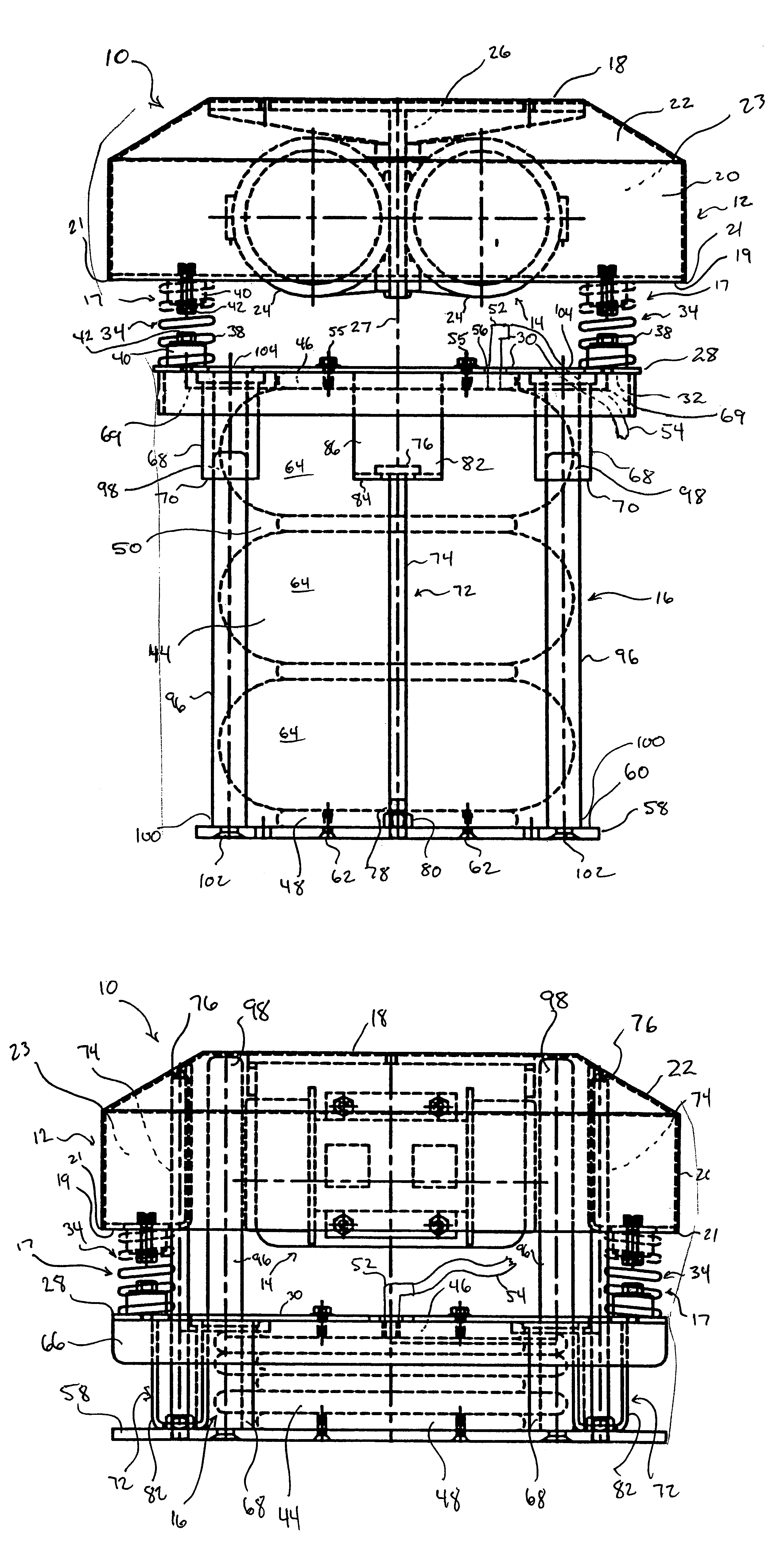
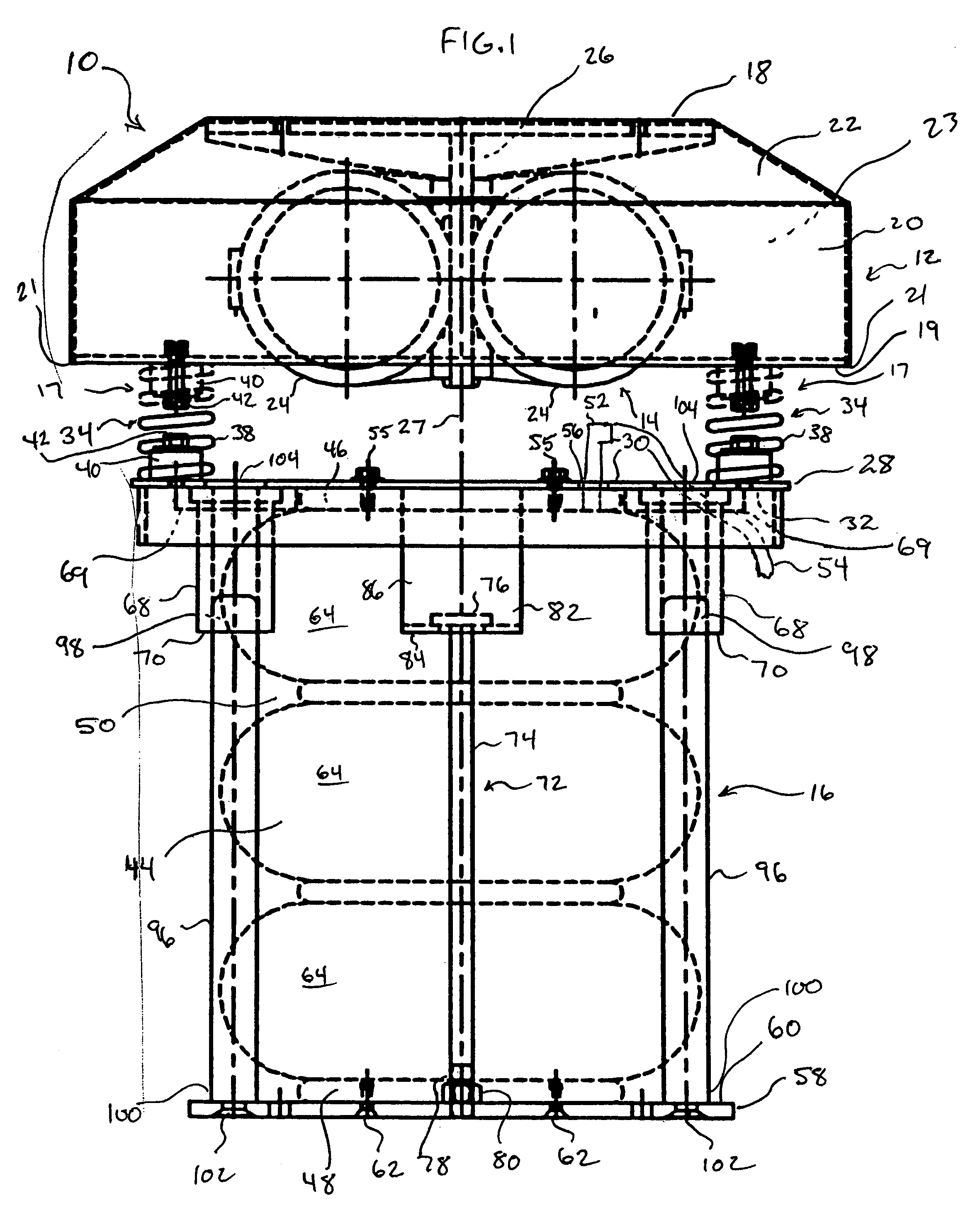
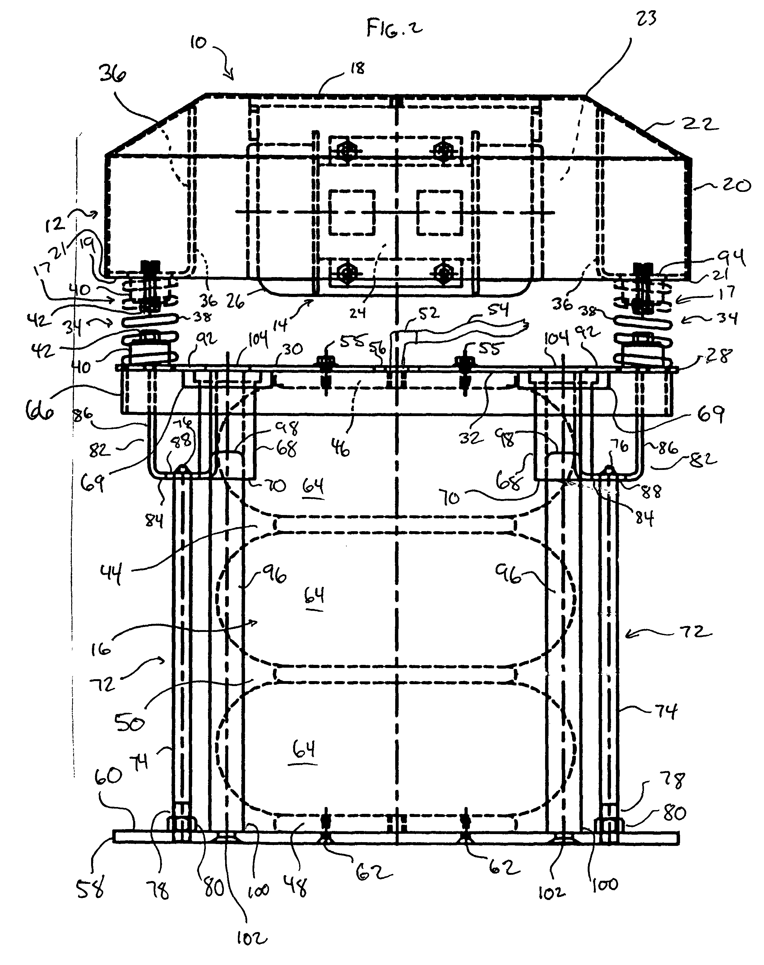
[0011]FIGS. 1 to 3 illustrate a preferred table assembly 10 according to the present invention.

[0012]Table assembly 10 comprises a bag support table 12, a vibrating device 14 for vibrating the bag support table 12, a lifting device 16 for raising and lowering the bag support table 12 and at least one resilient connector 17 through which the bag support table 12 and the lifting device 16 are connected. As shown in the drawings, the lifting device 16 is located below the bag support table 12.

[0013]The bag support table 12 and vibrating device 14 are similar to those described in prior U.S. Pat. Nos. 4,718,464 and 5,336,853, mentioned above. Specifically, the bag support table 12 is rectangular, preferably square, in plan view, having a rectangular upper surface 18, four vertical side surfaces 20, and four sloped side surfaces 22 connecting the vertical side surfaces 20 and the upper surface 18. The side surfaces 20, 22 extend outwardly and downwardly from the upper surface 18 to a low...


PUM

PropertyMeasurementUnit
heightaaaaaaaaaa
resilientaaaaaaaaaa
heightaaaaaaaaaa

Abstract

A vibrating table assembly for an apparatus for filling and weighing bulk bags comprises a bag support table, a vibrating device for vibrating the bag support table, and a lifting device for raising an lowering the bag support table, the lifting device being located below the bag support table. Preferably, the lifting device comprises a convoluted air bellows. Location of the lifting device below the table overcomes problems encountered with known bag filling apparatus where the bag support table and the lifting mechanism are connected to the frame of the apparatus.

Description

FIELD OF THE INVENTION[0001]The invention relates to apparatus for filling and weighing bulk bags, and particularly relates to vibrating table assemblies for use in such apparatus.BACKGROUND OF THE INVENTION[0002]Efficient filling and weighing of bulk bags (also known as flexible intermediate bulk containers) is performed with an apparatus on which a bulk bag is suspended by loops above a bag support table. During filling of the bag, the bag bottom is partly supported by the support table, which typically has a top portion shaped like a flattened, truncated pyramid. A pair of unbalanced counter-rotating motors are located inside the support table to vibrate and compact the contents of the bag as it is being filled.[0003]The bag support table is brought into contact with the bulk bag either by lowering the bag or raising the support table. Two types of apparatus in which the support table can be raised and lowered are disclosed in U.S. Pat. Nos. 4,718,464 and 5,336,853. In U.S. Pat. ...

Claims


Application Information

Patent Timeline
Patent Type & Authority Patents(United States)
IPC IPC(8): A47B85/00A47B9/00A47B1/04B65B1/08B65B1/22B65B1/32B65G65/32
CPCB65B1/08B65G65/32B65B1/32
Inventor MACKRILL, DONCACCIACARRO, CARMINEPANCHAL, VIREN
Owner SPIROFLOW SYST
Why Eureka
Try Eureka