Planing/chamfering attachment for a rotary hand tool

a technology of hand tools and attachments, applied in the field of hand tools, can solve problems such as large and heavy weigh

Active Publication Date: 2007-01-30
ROBERT BOSCH GMBH +1
View PDF28 Cites 6 Cited by
  • Summary
  • Abstract
  • Description
  • Claims
  • Application Information

AI Technical Summary

Problems solved by technology

However, such handheld planers are designed to perform commercial planing operations over an extended life and are therefore larger and heavier than is often needed for occasional use or for lighter or smaller planing or chamfering operations that may be carried out using a small rotary hand tool that is useful for performing many other types of operations.

Method used


Image

  • Planing/chamfering attachment for a rotary hand tool
  • Planing/chamfering attachment for a rotary hand tool
  • Planing/chamfering attachment for a rotary hand tool

Examples


Embodiment Construction

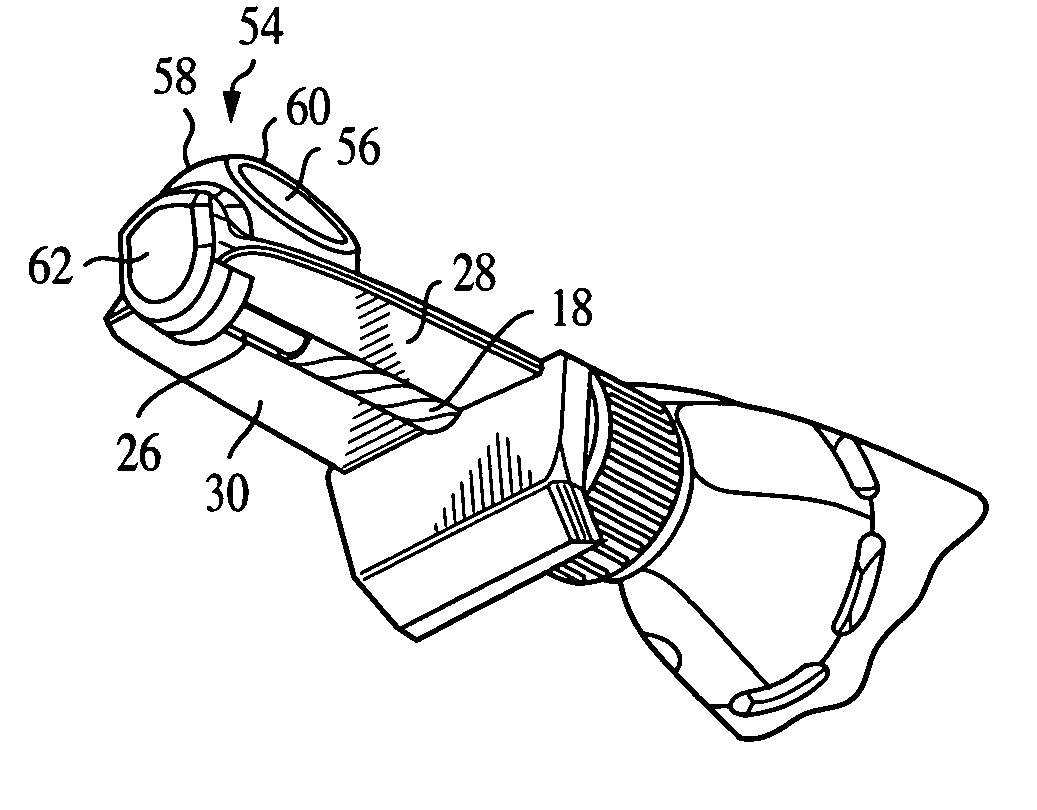
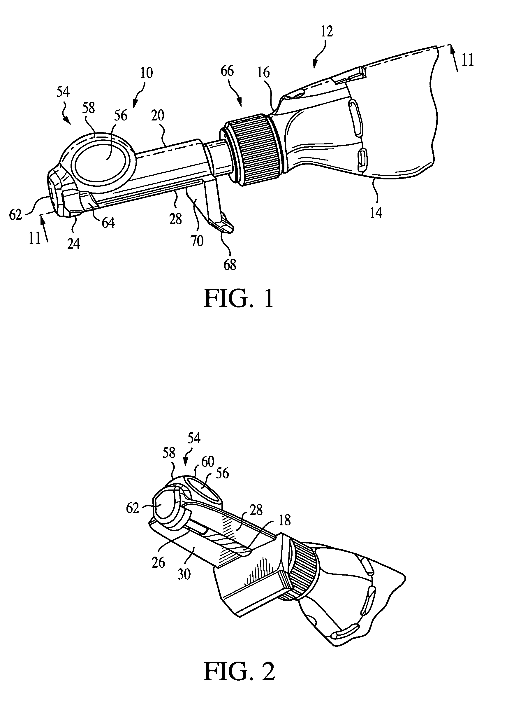
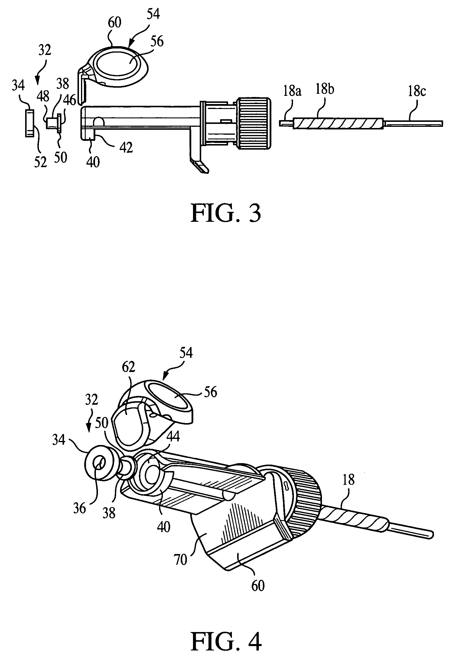
[0019]Turning now to FIG. 1, an embodiment of the present invention includes a planing attachment, designated generally at 10, for a rotary hand tool 12 of the type having a generally cylindrical body 14 with an output shaft 15 at a nose end 16 thereof to which a rotating cutting bit 18 (best shown in FIG. 2) is secured by a collet system (not shown) or other mounting mechanism, such as a chuck (not shown), and includes a pilot end (not shown) at an opposite end thereof. The collet system preferably includes a collet nut (not shown) and a collet (not shown).

[0020]The planing attachment 10 is configured at an attaching end to matingly engage the nose end of the rotary hand tool 12. The attachment 10 preferably includes a generally cylindrical housing 20 having an attaching end portion 22 (best shown in FIG. 6) and a planing tool end portion 24, wherein the attaching end portion is configured to matingly engage the nose end 16 of the rotary hand tool 12. The cutting bit 18 includes a ...


PUM

PropertyMeasurementUnit
angleaaaaaaaaaa
angleaaaaaaaaaa
lengthaaaaaaaaaa

Abstract

A planing attachment for a rotary hand tool of the type having a generally cylindrical body with an output shaft at a nose end thereof to which a cutting bit can be attached, the attachment being configured at an attaching end to matingly engage the nose end of the hand tool. The attachment includes a housing having an attaching end portion and a planing tool end portion, wherein the attaching end portion is configured to matingly engage the nose end of the rotary hand tool, and a leading plane and a trailing plane are configured wherein one of the planes is disposed on opposite sides of the cutting bit, and wherein the leading plane is elevated relative to the trailing plane by a distance proportional to the depth of cut made by the cutting bit. The attachment further includes a longitudinal cavity disposed between the leading plane and the trailing plane and is configured to receive the cutting bit therein, a cutting bit support disposed at the planing tool end portion of the attachment.

Description

BACKGROUND OF THE INVENTION[0001]The present invention generally relates to hand tools and more particularly to rotary hand tool accessories.[0002]Portable powered planers have long been used to trim a side or an end of a wooden door so that it will properly fit within a frame, among the many examples of planing and chamfering operations that woodworkers and artisans often perform. Many commercially available portable planing power tools typically include a rotatable cutter drum assembly in which a cutting blade is mounted in a housing assembly that has an electric motor. The drum assembly is disposed between a front shoe and a rear base plate, in a manner whereby the outer reach of the cutting blade is substantially at the same plane of the bottom of the base plate. The front shoe has a flat planar bottom surface that is vertically adjustable relative to the rear base plate to control the amount of material that will be removed as the planer is moved forwardly along a work piece du...

Claims


Application Information

Patent Timeline
Patent Type & Authority Patents(United States)
IPC IPC(8): B23C1/20B23C3/12B25F3/00B27CB27C1/10
CPCB23C1/20B23C3/12B25F3/00B27C1/10Y10T409/304144Y10T409/306608Y10T409/306496Y10T409/306552
Inventor BABER, BRAD M.
Owner ROBERT BOSCH GMBH
Why Eureka
Try Eureka