Al technical title is built by PatSnap Al team. It summarizes the technical point description of the patent document.
a ballast circuit and inductive coupling technology, applied in the field of ballasts, can solve the problems of complex replacement, large number of direct electrical connections, and difficulty in installing and removing load from ballast, and achieve the effect of small change regions
Inactive Publication Date: 2007-02-20
PHILIPS IP VENTURES BV
View PDF179 Cites 358 Cited by
Summary
Abstract
Description
Claims
Application Information
AI Technical Summary
This helps you quickly interpret patents by identifying the three key elements:
Problems solved by technology
Method used
Benefits of technology
[0013]An interesting feature of the inductively coupled ballast circuit is the inductive coupling. The series resonant tank circuit includes an inductive coupler. In one embodiment, the inductive coupler is positioned adjacent the secondary coil with an air gap therebetween to form an air core transformer. When voltage is applied to the inductive coupler, magnetic flux in the air gap induces voltage in the secondary coil thereby energizing the secondary load.
[0015]Yet another interesting feature involves the frequency of operation of the inductively coupled ballast circuit. Both the series resonant tank and the secondary load may be tuned by proper selection of components to operate at a similar resonant frequency. In addition, impedance matching between the series resonant tank and the secondary load may occur at the resonant frequency. Accordingly, power transfer from the inductive coupler to the secondary coil may be optimized at a resonant frequency to maximize power efficiency.
[0017]In another aspect, the present invention preferably includes a current limit circuit that monitors the ballast circuit and disables the ballast circuit if the current to the primary exceeds a desired threshold. The current limit circuit protects both the load and the ballast circuit from excessive current. The current limit circuit is preferably latched to keep the ballast circuit disabled until reset, for example, by a manual reset switch.
Problems solved by technology
Direct electrical connections present a number of problems.
First, direct electrical connections make it difficult to install and remove the load from the ballast.
If the ballast or the load is damaged, replacement is complicated by the permanent connections.
Removable connectors are also subject to corrosion and may be inadvertently or unintentionally disconnected, for example, by vibrations.
For example, in wet environments, exposed electrical connections are subject to a short circuit.
Third, direct electrical connections provide a direct and essentially unimpeded path for electricity to flow between the ballast and the load.
As a result, power surges and other potentially damaging abnormalities in one element can be directly transfer to the other, thereby permitting problems in one component to damage or even destroy the other.
First, inductive couplings do not include permanent or removable physical connectors.
Unfortunately, conventional inductively coupled ballasts suffer from a number of problems associated primarily with efficiency.
A square waveform has relatively small regions of change and therefore provides relatively inefficient transfer of power.
Method used
Image
Click on the blue label to locate the original text in one second.
Reading with bidirectional positioning of images and text.
Examples
Embodiment Construction
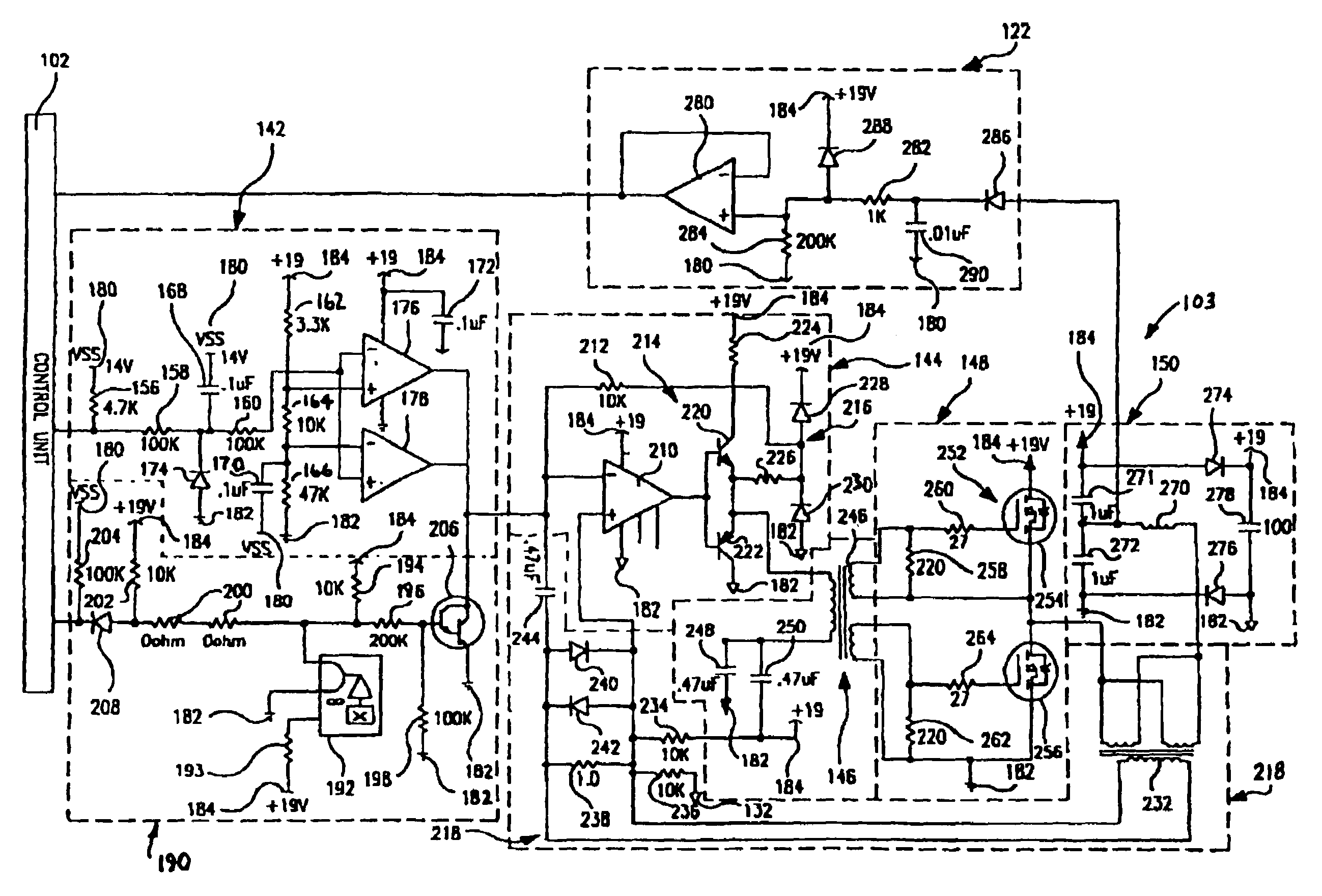
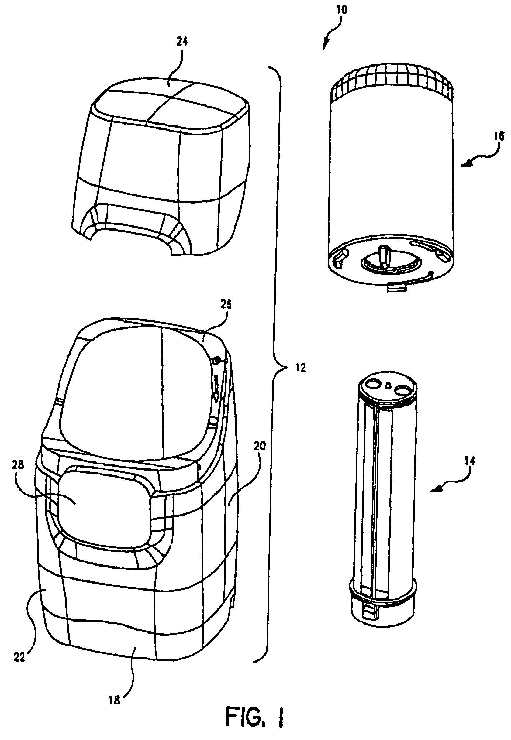
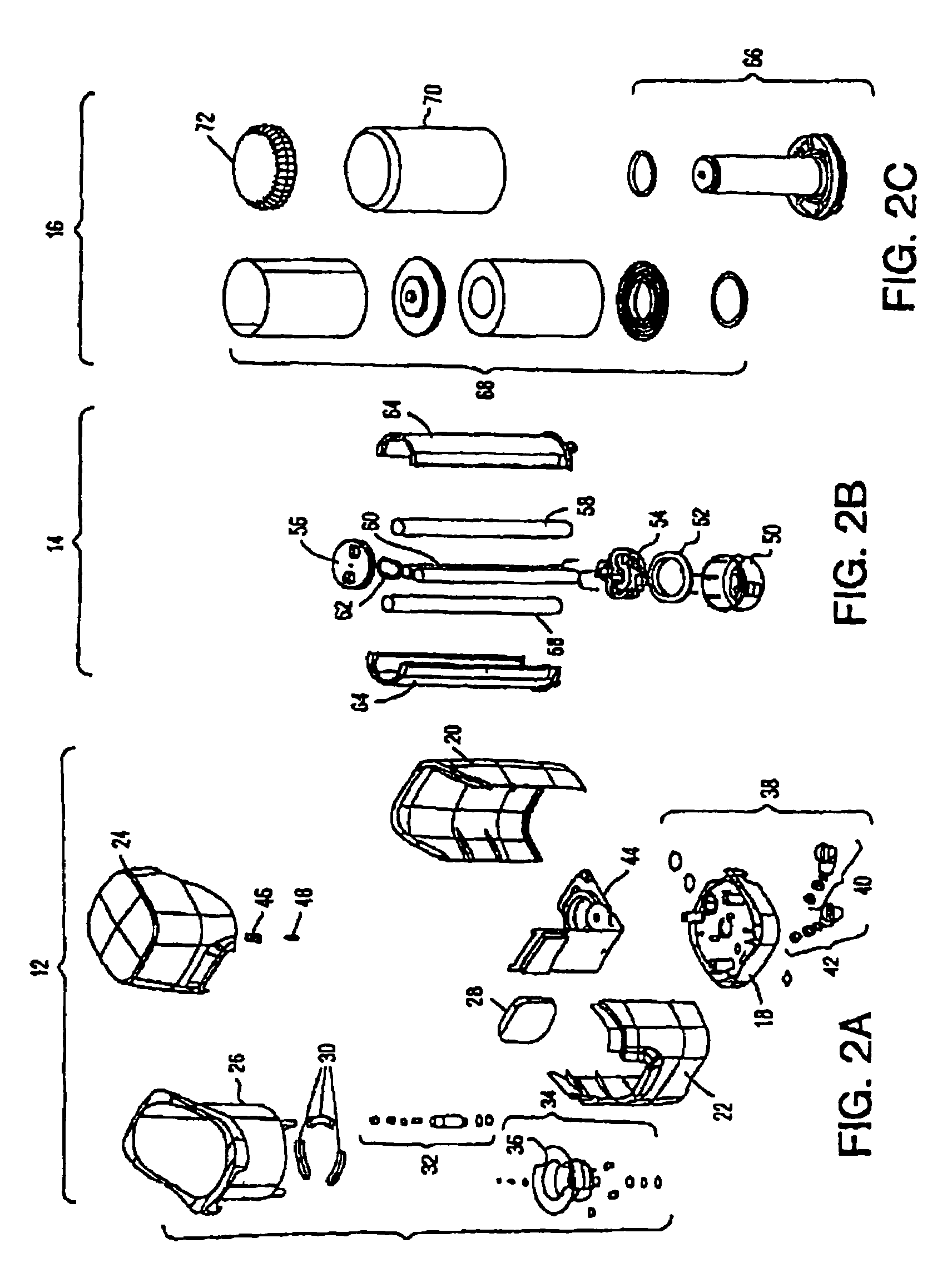
[0037]The present invention is directed to an inductively coupled ballast circuit that is capable of providing power to a wide variety of electrically powered components in numerous applications. For purposes of disclosure, embodiments of the ballast circuit will be described in connection with a water treatment system, and more specifically in connection with the powering of an ultraviolet lamp in a water treatment system. Although described in connection with this particular application, the present invention is well-suited for use in providing power to other types of lamps, such as incandescent, fluorescent and halogen lamps used in numerous lighting applications, such as indoor and outdoor light fixtures, desk lamps, outdoor signage, decorative lighting, automotive lighting, underwater lighting, intrinsically safe lighting, and landscape lighting, to name only a few lighting configurations and applications. The present invention is also well suited for providing power to non-lig...
PUM
Property
Measurement
Unit
resonant frequency
aaaaa
aaaaa
diameter
aaaaa
aaaaa
diameter
aaaaa
aaaaa
Abstract
A ballast circuit is disclosed for inductively providing power to a load. The ballast circuit includes an oscillator, a driver, a switching circuit, a resonant tank circuit and a current sensing circuit. The current sensing circuit provides a current feedback signal to the oscillator that is representative of the current in the resonant tank circuit. The current feedback signal drives the frequency of the ballast circuit causing the ballast circuit to seek resonance. The ballast circuit preferably includes a current limit circuit that is inductively coupled to the resonant tank circuit. The current limit circuit disables the ballast circuit when the current in the ballast circuit exceeds a predetermined threshold or falls outside a predetermined range.
Description
[0001]This application is a continuation of U.S. patent application Ser. No. 10 / 246,155 entitled “Inductively Coupled Ballast Circuit,” filed Sep. 18, 2002, now U.S. Pat. No. 6,825,620 B2; which is a continuation-in-part of U.S. patent application Ser. No. 10 / 175,095 entitled “Fluid Treatment System,” filed Jun. 18, 2002, now U.S. Pat. No. 6,673,250; which is a continuation-in-part of U.S. patent application Ser. No. 09 / 592,194 entitled “Fluid Treatment System,” filed Jun. 12, 2000, now U.S. Pat. No. 6,436,299, U.S. patent application Ser. No. 09 / 592,194 (now U.S. Pat. No. 6,436,299) claims the benefit under 35 U.S.C. §119(e) of U.S. Provisional Patent Application Ser. No. 60 / 140,159 entitled “Water Treatment System with an Inductively Coupled Ballast,” filed Jun. 21, 1999 and U.S. Provisional Patent Application Ser. No. 60 / 140,090 entitled “Point-of-Use Water Treatment System,”filed Jun. 21, 1999.[0002]This application hereby incorporates by reference U.S. patent application Ser. N...
Claims
Application Information
Patent Timeline
Application Date:The date an application was filed.
Publication Date:The date a patent or application was officially published.
First Publication Date:The earliest publication date of a patent with the same application number.
Issue Date:Publication date of the patent grant document.
PCT Entry Date:The Entry date of PCT National Phase.
Estimated Expiry Date:The statutory expiry date of a patent right according to the Patent Law, and it is the longest term of protection that the patent right can achieve without the termination of the patent right due to other reasons(Term extension factor has been taken into account ).
Invalid Date:Actual expiry date is based on effective date or publication date of legal transaction data of invalid patent.