

Broadband high power amplifier
- Summary
- Abstract
- Description
- Claims
- Application Information
AI Technical Summary
Benefits of technology
Problems solved by technology
Method used
Image

Examples
Embodiment Construction
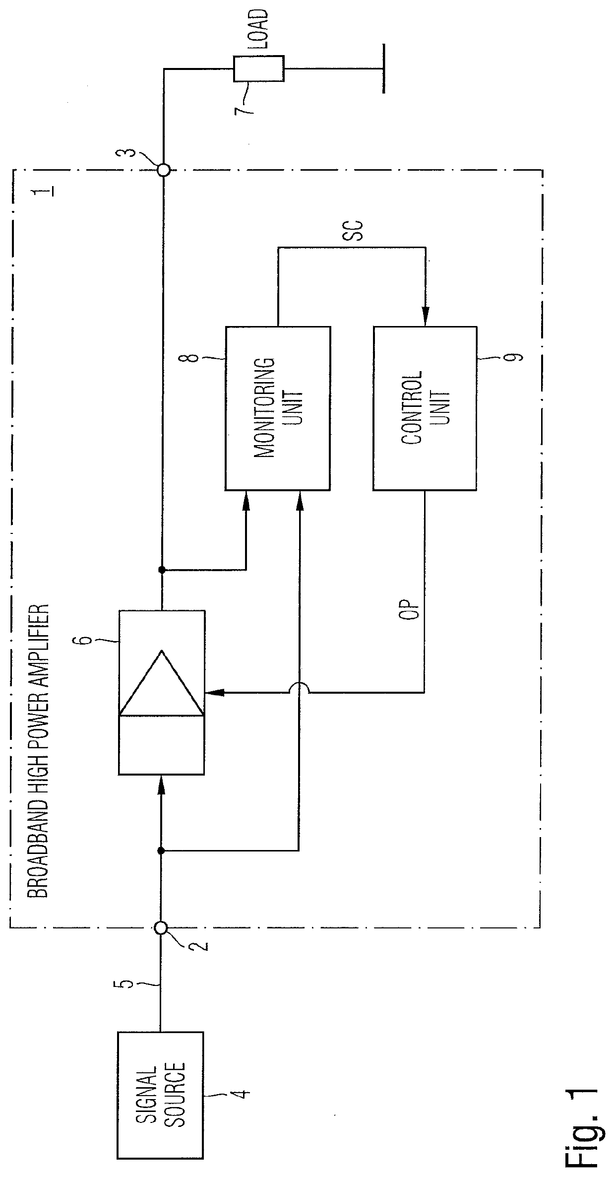
[0051]FIG. 1 shows a block diagram of a possible exemplary embodiment of a broadband high power amplifier 1 according to the first aspect of the present invention. The broadband high power amplifier 1 comprises a signal input 2 and a signal output 3. The signal input 2 receives a signal from a signal source 4 via a signal line 5. The broadband high power amplifier 1 comprises at least one amplifier stage 6 adapted to amplify the received input signal and to output the amplified signal at the signal output 3 of the broadband high power amplifier 1. As can be seen in FIG. 1, an external load 7 is connected to the signal output 3 of the broadband high power amplifier 1.
[0052]The broadband high power amplifier 1 comprises a monitoring unit 8 adapted to monitor signal characteristics of the input signal applied to the amplifier stage 6 and signal characteristics of the amplified output signal generated by the amplifier stage 6. The monitoring unit 8 is adapted to supply the monitored sig...
PUM
 Abstract
Description
Claims
Application Information