Ultraviolet detector optical subdivision device

An ultraviolet detector and optical technology, applied in the field of ultraviolet detectors, can solve the problems of inability to maintain the instrument on site, high processing requirements, unfavorable convenience, etc., and achieve the effects of correcting the motor rotation angle, reducing production costs, and optimizing operations

Active Publication Date: 2015-07-15
ZHEJIANG FULI ANALYTICAL INSTR
View PDF12 Cites 0 Cited by
  • Summary
  • Abstract
  • Description
  • Claims
  • Application Information

AI Technical Summary

Problems solved by technology

Although such a device realizes the subdivision of the optical path system, it has more unreliability. First, the structure uses more mechanical parts, such as screw rods, couplings, sinusoidal rods, screw racks, etc., so it is difficult for processing The requirements are very high; secondly, more parts are inefficient in the assembly process, and there are high requirements on the skill level of workers and tooling equipment. Therefore, the instrumen

Method used


Image

  • Ultraviolet detector optical subdivision device
  • Ultraviolet detector optical subdivision device
  • Ultraviolet detector optical subdivision device

Examples


Example Embodiment

[0023] The present invention will be further described below with specific examples, see figure 2 —4:

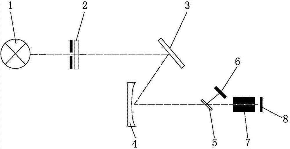
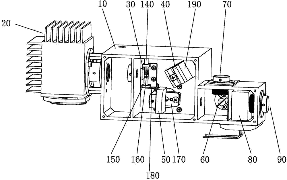
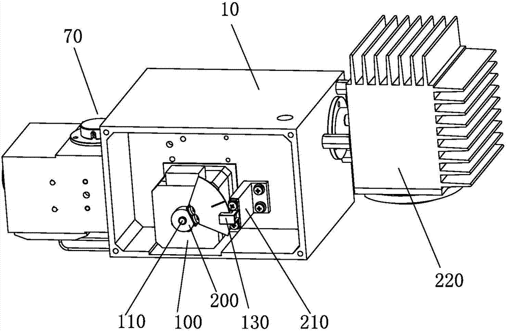
[0024] An ultraviolet detector optical subdivision device, including a light source 20, a filter 30, a reflector 40, a concave grating 50, a half mirror 60, a reference photocell 70, a current After the cell 80 and the sample photocell 90, the light of the lamp source 20 sequentially passes through the filter 30, the reflector 40, the concave grating 50, the half mirror 60, and from the half mirror 60 through the reference photocell 70 and It flows through the cell 80 and the sample photocell 90. The groove grating 80 is driven to rotate by the stepping motor 100. The motor shaft 110 is provided with an optocoupler barrier 120 that rotates synchronously with the groove grating 80. One side of 120 is provided with an optocoupler 130 that cooperates with the optocoupler barrier 120, and each time the power is turned on, the optocoupler 130 and the optocoupler barrier 120 coopera...


PUM


Abstract

The invention belongs to the technical field of ultraviolet detectors and in particular relates to an ultraviolet detector optical subdivision device. The device comprises a light source, a glass filter, a reflector, a concave grating, a half-transparent and half reflecting mirror, a reference photocell, a flow-through pool and a sample photocell which are arranged on a light path box body, wherein light of the light source sequentially passes through the glass filter, the reflector, the concave grating and the half-transparent and half reflecting mirror and respectively passes through the reference photocell, the flow-through pool and the sample photocell from the half-transparent and half reflecting mirror; the concave grating is driven to rotate by virtue of a stepping motor; an optical coupler stopper which synchronously rotates with the concave grating is arranged on the rotating shaft of the motor; an optical coupler is arranged on one side of the optical coupler stopper; and the optical coupler and the optical coupler stopper are matched with an optical coupler detection zero point to realize origin orientation of the concave grating during electrification each time. According to the device disclosed by the invention, the defects of optical units of the conventional detector are overcome, the stability of the instrument is improved, the operation of the instrument is optimized, the production cost of the instrument is reduced, and the number of parts is simplified.

Description

Technical field: [0001] The invention belongs to the technical field of ultraviolet detectors, in particular to an optical subdivision device of ultraviolet detectors. Background technique: [0002] In a traditional liquid chromatography instrument, a UV detector is generally equipped, including: a light source 1, a filter mirror 2, a mirror 3, a concave grating 4, a half-mirror 5, a reference photocell 6, and a flow-through cell 7 And sample photocell 8. It measures the change of the sample concentration by quickly recording the change of the absorbance of the mobile phase at a specific wavelength, so the optical unit is the core component of the instrument (see figure 1 ). Generally, the wavelength range required by chromatographic instruments is 200nm to 700nm, and the rotation angle of the grating is less than 30 degrees. Therefore, the traditional optical unit uses the mechanical structure of a sinusoidal screw to subdivide the rotation angle of the grating, and conve...

Claims


Application Information

Patent Timeline
IPC IPC(8): G01N30/74
Inventor 江仁谦夏亚兵
Owner ZHEJIANG FULI ANALYTICAL INSTR
Why Eureka
Try Eureka