Systems and methods for power production including ion transport components

a technology of power production system and transport components, applied in the direction of machines/engines, turbine/propulsion fuel heating, lighting and heating apparatus, etc., can solve the problems of increasing the capital cost of the power production system and consuming a large quantity of power, and achieve significant cost savings in equipment costs and operating costs. , the effect of high purity oxygen

Active Publication Date: 2019-04-16
8 RIVERS CAPTTAL LLC
View PDF14 Cites 7 Cited by
  • Summary
  • Abstract
  • Description
  • Claims
  • Application Information

AI Technical Summary

Benefits of technology

[0006]The systems and methods of the present disclosure can eliminate the need for one or more pieces of equipment that has been believed to be necessary for high efficiency oxyfuel combustion, such as a cryogenic air separation unit to provide high purity oxygen and / or a high pressure oxyfuel combustor to heat a pressurized working fluid stream prior to expansion for power production. The elimination of such elements can provide for significant cost savings both in equipment costs and operating costs. The presently disclosed power cycles can provide for operation of the power producing turbine at a much lower inlet temperature which will allow the possible elimination of internal CO2 cooling streams within the turbine blades and the inner turbine casing with consequent increase in turbine efficiency and reduction in capital cost.
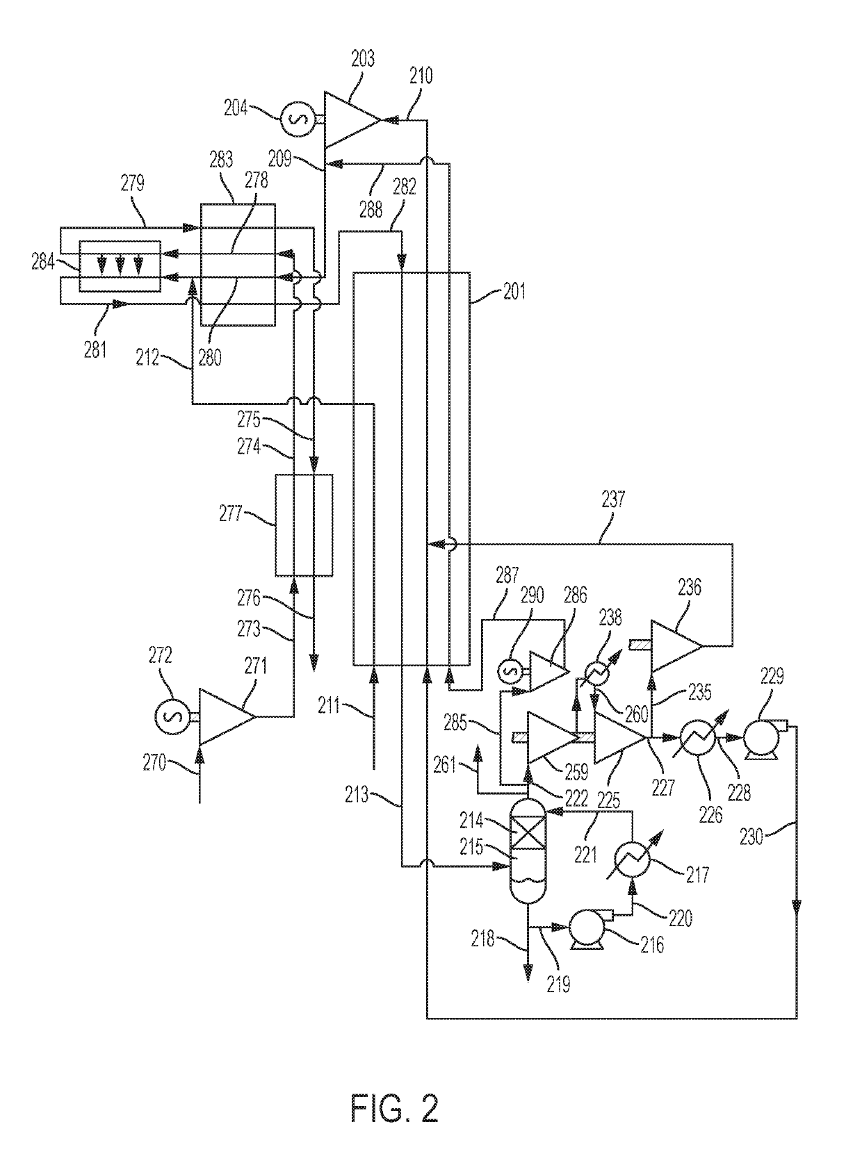
[0007]In one or more embodiments, the present systems and methods can eliminate the need for a high-pressure fuel gas compressor by introducing fuel gas into the system at the turbine discharge pressure. For example, a natural gas fuel may be provided directly from the natural gas pipeline at approximately 30 bar pressure.
[0008]In still further embodiments, the present systems and methods can eliminate the need for a separate dilution of the supplied oxygen in order to control the adiabatic flame temperature in the combustor. For example, known systems can mix CO2 with the oxygen stream, and this can require a separate CO2+O2 compression train and a separate stream in the recuperative heat exchanger. According to embodiments of the present disclosure, however, there is no requirement for a CO2+O2 compression train.
[0011]In one or more embodiments, the efficiency of a power production cycle can be maximized by operating the cycle at the temperature limitation imposed by the recuperator heat exchanger design limitations. For example, an operating temperature range of about 750° C. to about 850° C. for a turbine inlet temperature is presently the upper limit for a high pressure turbine operating without internal cooling of the blades or the inner casing (but could involve some protective coatings applied internally). Reducing turbine inlet temperature from the typical upper range of about 1100° C. to 1200° C. to a lower range of about 750° C. to 850° C. results in a significant drop in the power output for a fixed turbine inlet flow. Surprisingly, this does not result in a corresponding large drop in the overall thermal efficiency of a power production cycle according to the present disclosure. Such thermal efficiency can be in the range of about 52% to about 54% (LHV basis) based on current component design limitations and optimized performance. A system operating under conditions as described herein can retain the ability to capture close to 100% of the CO2 derived from the fuel gas combustion. The gas turbine integration allows 100% CO2 capture from fuel gas entering the ITM combustor to power the power production cycle. The CO2 derived from gas turbine fuel input would normally be vented to the atmosphere. This results in a reduction in overall CO2 capture for a maximum sized gas turbine optionally integrated with the presently disclosed system to a range of about 60% to about 70%.
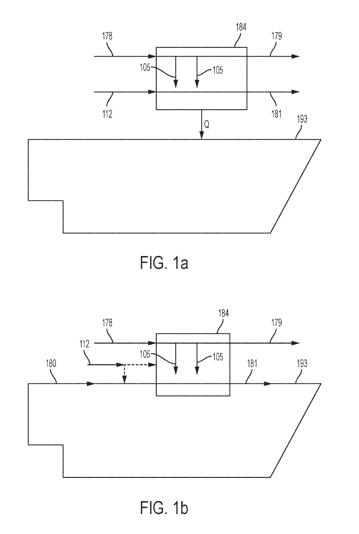
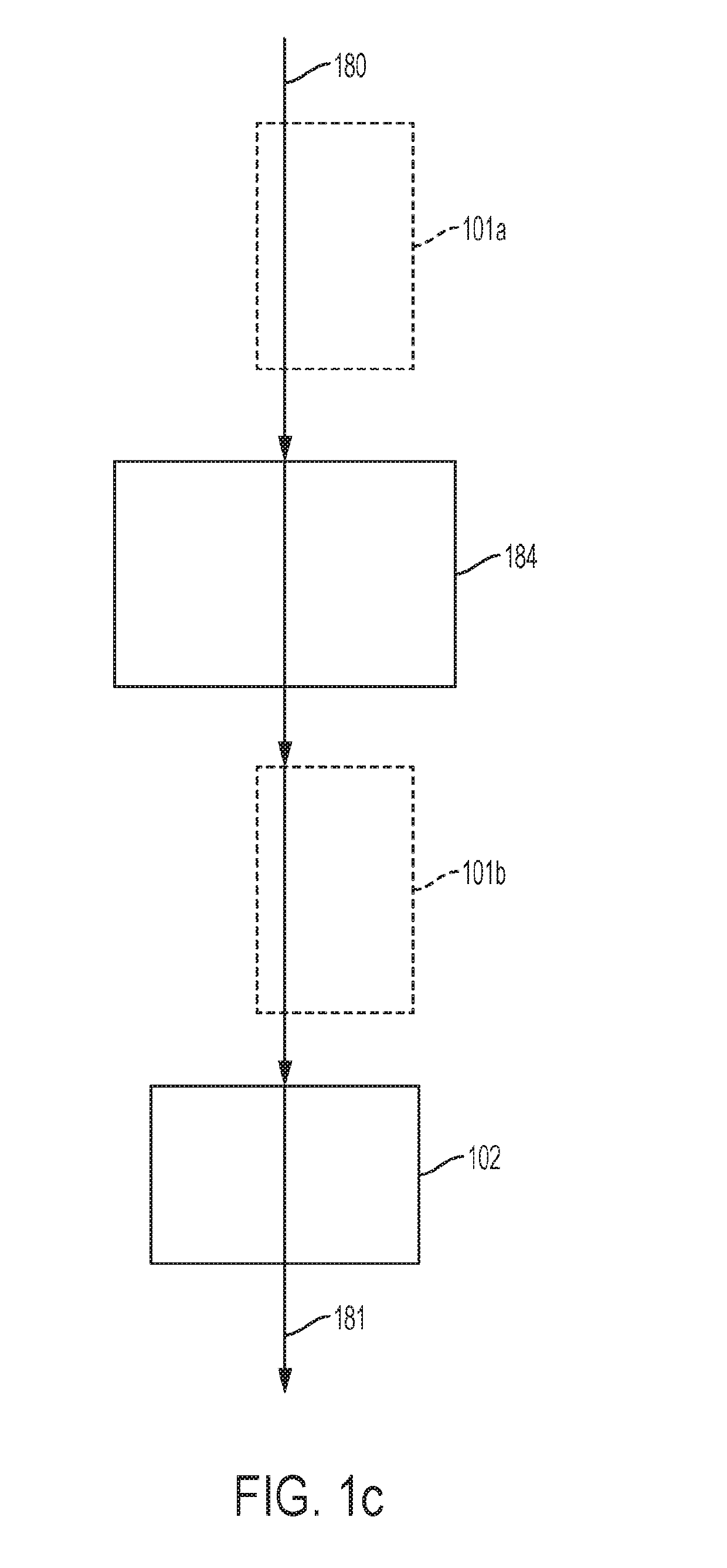
[0013]In one or more embodiments, a high temperature ceramic oxygen ion transport membrane can be used to transfer oxygen from an O2 containing stream (preferably a heated stream and preferably a low pressure stream) to a stream which contains fuel components (e.g., CH4, H2, CO, high molecular weight hydrocarbons, and mixtures of these components) and optionally CO2 (which stream can be heated and can be at a high pressure). The resulting transferred O2 oxidizes the fuel producing heat and CO2 plus H2O products. The heat released raises the temperature of the CO2 and combustion products. If desired, the ITM can be configured to only partially combust or oxidize one or more fuel components. For example, a carbonaceous fuel may be partially combusted or oxidized to form at least CO as a partial oxidation product.

Problems solved by technology

The inclusion of an oxygen plant significantly increases the capital cost of a power production system operating as described above and also consumes a large quantity of power during operation of the power production cycle.

Method used


Image

  • Systems and methods for power production including ion transport components
  • Systems and methods for power production including ion transport components
  • Systems and methods for power production including ion transport components

Examples


Embodiment Construction

[0088]The present disclosure will now be described more fully hereinafter with reference to the accompanying drawings, in which some, but not all implementations of the disclosure are shown. Indeed, various implementations of the disclosure may be expressed in many different forms and should not be construed as limited to the implementations set forth herein; rather, these exemplary implementations are provided so that this disclosure will be thorough and complete, and will fully convey the scope of the disclosure to those skilled in the art. For example, unless otherwise indicated, something being described as being a first, second or the like should not be construed to imply a particular order. Also, something may be described as being above something else (unless otherwise indicated) may instead be below, and vice versa; and similarly, something described as being to the left of something else may instead be to the right, and vice versa. As used in the specification, and in the a...


PUM


Abstract

The present disclosure relates to systems and methods for power production utilizing an ion transfer membrane (ITM) unit. An air stream and a fuel stream can be passed through the ITM unit so that the fuel is at least partially oxidized or combusted to form an outlet stream comprising CO2. The CO2 stream can be compressed and expanded to generate power.

Description

CROSS-REFERENCE TO RELATED APPLICATIONS[0001]The present application claims priority to U.S. Provisional Patent App. No. 62 / 381,907, filed Aug. 31, 2016, the disclosure of which is incorporated herein by reference.FIELD OF THE DISCLOSURE[0002]The present disclosure is directed to systems and methods for power production. In particular, power production may be carried out wherein oxygen for use in fuel combustion is at least partially provided by oxygen diffusion through an oxygen ion transport membrane.BACKGROUND[0003]Systems and methods for power generation utilizing combustion of carbonaceous or hydrocarbon fuel(s) with carbon dioxide as a working fluid are described in U.S. Pat. No. 8,596,075 to Allam et al., which is incorporated herein by reference. Such systems and methods utilize a high-pressure recuperative Brayton system with CO2 as a working fluid wherein substantially pure oxygen is used for the combustion of fuel at high pressures (e.g., approximately 200 bar to 400 bar)...

Claims


Application Information

Patent Timeline
Patent Type & Authority Patents(United States)
IPC IPC(8): F02C3/34F25J3/04F02C7/224F02C6/02F02C1/06F23L7/00F02C3/30
CPCF02C3/34F02C1/06F02C3/305F02C6/02F23L7/007F25J3/04018F25J3/04066F02C7/224F05D2260/61F05D2220/76Y02E20/16Y02E20/34F02C7/222
Inventor ALLAM, RODNEY JOHNBROWN, JR., GLENN WILLIAMHOFF, BENJAMIN
Owner 8 RIVERS CAPTTAL LLC
Why Eureka
Try Eureka