Spanner

a spanner and hammer head technology, applied in the field of spanners, can solve the problems of reducing working efficiency and affecting the use of spanners, and achieve the effect of reducing the size of the spanner head

Inactive Publication Date: 2007-03-13
CHOI OCK SOON
View PDF5 Cites 9 Cited by
  • Summary
  • Abstract
  • Description
  • Claims
  • Application Information

AI Technical Summary

Problems solved by technology

However, certain working conditions require only a spanner.
Being different from a ratchet box wrench, a conventional spanner is not capable of tightening or releasing a bolt continually in one direction, therefore, a user has to insert a bolt head within the head of the spanner to be engaged with the bolt head repeatedly each time after turning the spanner at a predetermined angle, for example 60 degrees for tightening or releasing a bolt or nut, and which would decrease the working efficiency.
However, these spanners have a problem that the construction of the spanner head become complex since a ratchet mechanism itself has a complex construction, accordingly the volume of the spanner head becomes too large, which makes the spanner loose its own merit of being convenient for operation in a slim working space.
In the mean time, the conventional spanner has another problem that respective distal ends of two jaws are opened parallel to each other so that the spanner is readily disengaged from the bolt head during operation, and this is quite inconvenient especially when a user holds the spanner vertically during operation for tightening or releasing a bolt or nut since he has to urge the spanner upwardly in order for turning the spanner.

Method used


Image

  • Spanner
  • Spanner
  • Spanner

Examples


first embodiment

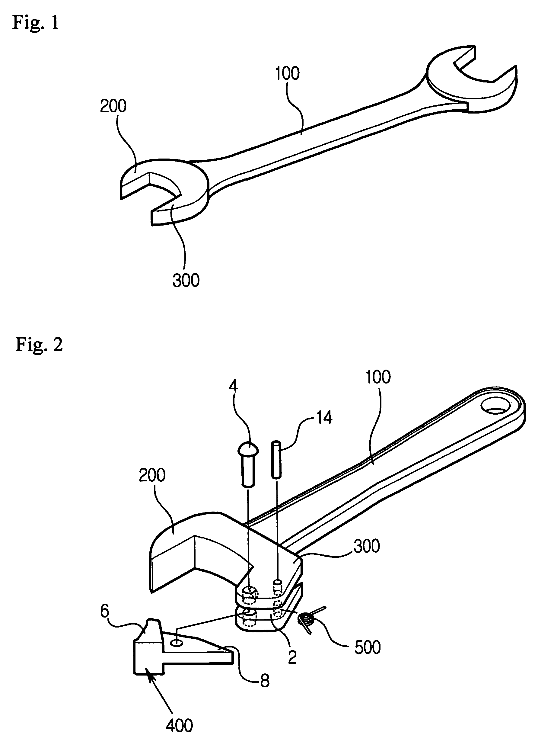
[0031]FIG. 2 is an exploded perspective view illustrating a spanner according to the present invention;

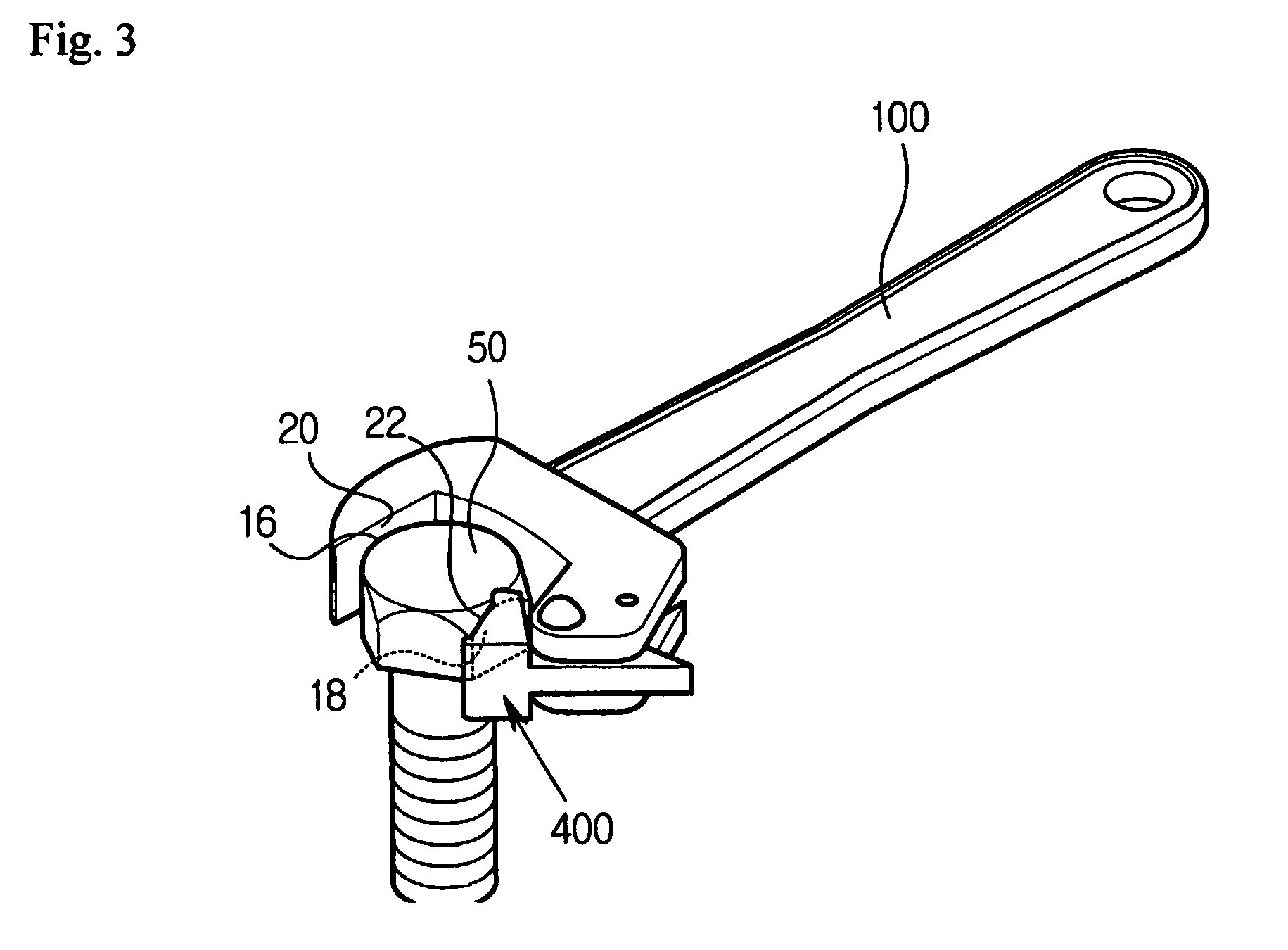
[0032]FIG. 3 is a perspective view illustrating a state that a bolt head is inserted within the spanner according to the first embodiment of the present invention;

[0033]FIG. 4 is a fragmentary plan view illustrating the spanner according to the first embodiment of the present invention;

[0034]FIG. 5 is a fragmentary plan view illustrating locations of the toggle bar and the recess formed on the second jaw of the spanner according to the first embodiment of the present invention;

[0035]FIG. 6 is a fragmentary plan view illustrating a state that the toggle bar of the spanner is swung upwardly in counter clockwise direction (as indicated by arrow A5 in FIG. 6) and just in contact with a bolt head, when the spanner is turned in counter clockwise direction (as indicated by arrow A4 in FIG. 4) which is a direction for a bolt to be released;

second embodiment

[0036]FIG. 7 is an exploded perspective view illustrating a spanner according to the present invention;

[0037]FIG. 8 is a perspective view illustrating a state that a bolt head is inserted within the spanner according to the second embodiment of the present invention;

[0038]FIG. 9 is a fragmentary plan view illustrating the spanner according to the second embodiment of the present invention;

third embodiment

[0039]FIG. 10 is a perspective view illustrating a state that a bolt head is inserted within a spanner according to the present invention;


PUM


Abstract

Disclosed is a spanner which is generally used as a typical tool for tightening or releasing a bolt. The spanner is capable of tightening or releasing a bolt continually in one direction by the effect of a toggle bar (400) pivotally mounted on a jaw of two jaws (200, 300) of the spanner head in a state that the toggle bar is urged to pivot toward one direction. A protrusion (30, 32) is formed on a distal end of the other jaw of the spanner head for gripping an angular portion of the bolt head so that it is possible to prevent the spanner head being readily disengaged from the bold head.

Description

BACKGROUND OF THE INVENTION[0001]1. Field of the invention[0002]The present invention relates to a spanner generally used as a typical tool for tightening or releasing a hexagonal headed bolt or nut, more particularly to a spanner capable of tightening or releasing a bolt continually in one direction by the effect of a toggle bar pivotally mounted on a jaw of two jaws of the spanner head in a state that the toggle bar is urged to pivot toward one direction.[0003]According to the present invention, if a user turns the spanner in clockwise direction, the rotating force of the spanner is applied to the bolt head so that the bolt head is tightened or released by the spanner, whereas, if a user turns the spanner in counter clockwise direction, the toggle bar is swung upwardly to be idle from the bolt head so that the rotating force of the spanner is not applied to the bolt head, thereby the spanner is capable of tightening or releasing a bolt continually in one direction while maintainin...

Claims


Application Information

Patent Timeline
Patent Type & Authority Patents(United States)
IPC IPC(8): B25B13/28B25B13/08B25B13/10B25B13/46
CPCB25B13/08B25B13/46B25B13/28
Inventor CHOI, OCK-SOON
Owner CHOI OCK SOON
Why Eureka
Try Eureka