Seal container

a container and seal technology, applied in the field of seal containers, can solve the problems of affecting the sealing effect,

Inactive Publication Date: 2007-04-17
JUMPER ENTERPRISE
View PDF12 Cites 48 Cited by
  • Summary
  • Abstract
  • Description
  • Claims
  • Application Information

AI Technical Summary

Problems solved by technology

The above seal container has the following disadvantages:1. It is difficult to make a mold for the lid 10 because the lid 10 has the cavities 101.2. Dust will accumulate in the space between both of the pressing elements 102 as well as the space between the pressing elements 102 and the lid 10, and the lid 10 is difficult to clean because of the structure.
In other words, the seal container isn't convenient to use.
However, the bumps 601 will wear owing to external force thereon that is caused when the knob member 50 is turned, therefore they get damaged after the seal container is used for a certain period of time.
Consequently, the seal container isn't convenient to use.

Method used


Image

  • Seal container
  • Seal container
  • Seal container

Examples


Embodiment Construction

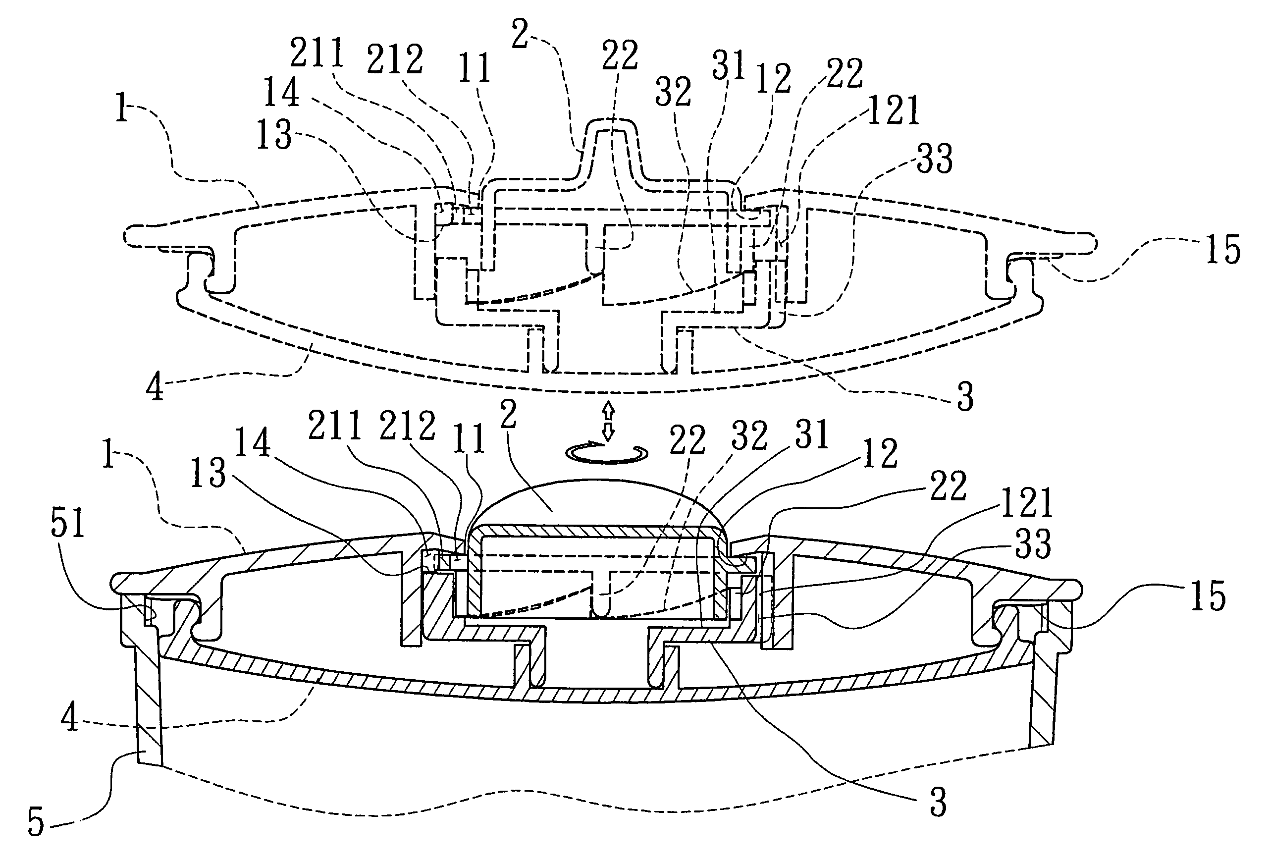
[0027]Referring to FIGS. 5 and 7, a preferred embodiment of a seal container includes a lid 1, a knob member 2, a depressing member 3, a soft seal member 4, and a container body 5.

[0028]The lid 1 has a central hole 11, an annular portion on a lower side, a holding room 12 defined by the annular portion, several guide bumps 121 spaced apart on an inner side of the annular portion, a pair of locating bumps 13 between every two adjacent ones of the guide bumps 121, and locating projections 15 on an edge of a lower side thereof; each of the locating bumps 13 includes two sloping sides, which together form an angle; each pair of locating bumps 13 define a holding space 14 in between.

[0029]The knob member 2 has a central raised portion, a rim 21 around the central raised portion, several touching projections 22 spaced apart on an annular side under the rim 21, and an engaging projection 211 on an edge of the rim 21. An elongated hole 212 is formed near to the engaging projection 211 on th...


PUM


Abstract

A seal container includes a container, a lid, a knob fitted on the lid, a soft seal fitted over a lower side of the lid, and a depressing member arranged under the knob and connected with a middle of the seal at a lower end; the depressing member has several slopes on an annular edge; the knob has projections, which are spaced on an annular edge, and touch the slopes respectively; the depressing member will move down, and the seal will be depressed at the middle to reduce in circumference immediately after the knob is turned to such a position that the projections touch higher ends of the slopes; the seal will stretch to a normal shape to seal the container immediately after the knob is turned to such a position that the projections touch lower ends of the slopes.

Description

BACKGROUND OF THE INVENTION[0001]1. Field of the Invention[0002]The present invention relates to a seal container, more particularly one, which includes a seal member for a container body, and a knob usable for changing the seal member to a sealing shape as well as an unsealing shape, and which is structured in such a way as to be convenient to use and have extended service life.[0003]2. Brief Description of the Prior Art[0004]Referring to FIGS. 1 and 2, a conventional seal container includes a lid 10, a soft seal member 20, and a container body 30. The lid 10 has cavities 101, and a through hole under the cavities 101. Two pressing elements 102 are held in the cavities, and pivoted to the lid 10. The soft seal member 20 is fitted over a lower end of the lid 10 to face the through hole of the lid 10 at a middle portion. The pressing elements 102 will be away from the soft seal member 20, and the seal member 20 will be in a normal shape, in which shape it can stretch and closely touc...

Claims


Application Information

Patent Timeline
Patent Type & Authority Patents(United States)
IPC IPC(8): B65D39/12B65D53/00
CPCB65D39/12
Inventor HSU, CHUN-FENG
Owner JUMPER ENTERPRISE
Why Eureka
Try Eureka