Wheel lift system

a technology of lifting system and wheel hub, which is applied in the direction of lifting device, wheel mounting apparatus, transportation and packaging, etc., can solve the problems of inconvenient operation of conventional wheel lifting device, inconvenient lifting and positioning of wheel and tire onto wheel hub, and relatively complex and expensive conventional wheel lift devices

Inactive Publication Date: 2007-04-24
WHEELFLOAT
View PDF33 Cites 25 Cited by
  • Summary
  • Abstract
  • Description
  • Claims
  • Application Information

AI Technical Summary

Benefits of technology

[0009]In view of the foregoing disadvantages inherent in the known types of wheel lift devices now present in the prior art, the present invention pro

Problems solved by technology

Conventional wheel lift devices are relatively complex and expensive.
In addition, conventional wheel lift devices are relatively cumbersome to operate.
While these devic

Method used


Image

  • Wheel lift system
  • Wheel lift system
  • Wheel lift system

Examples


Embodiment Construction

A. Overview

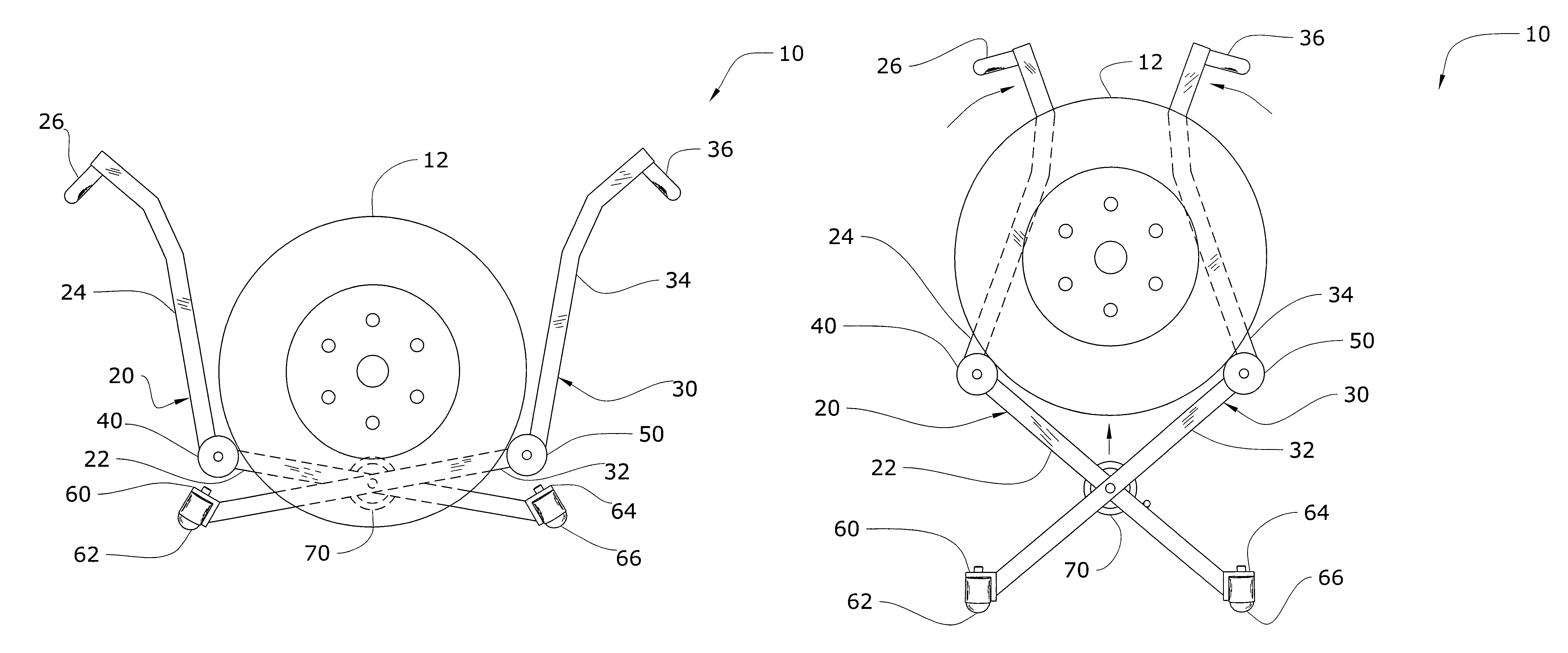
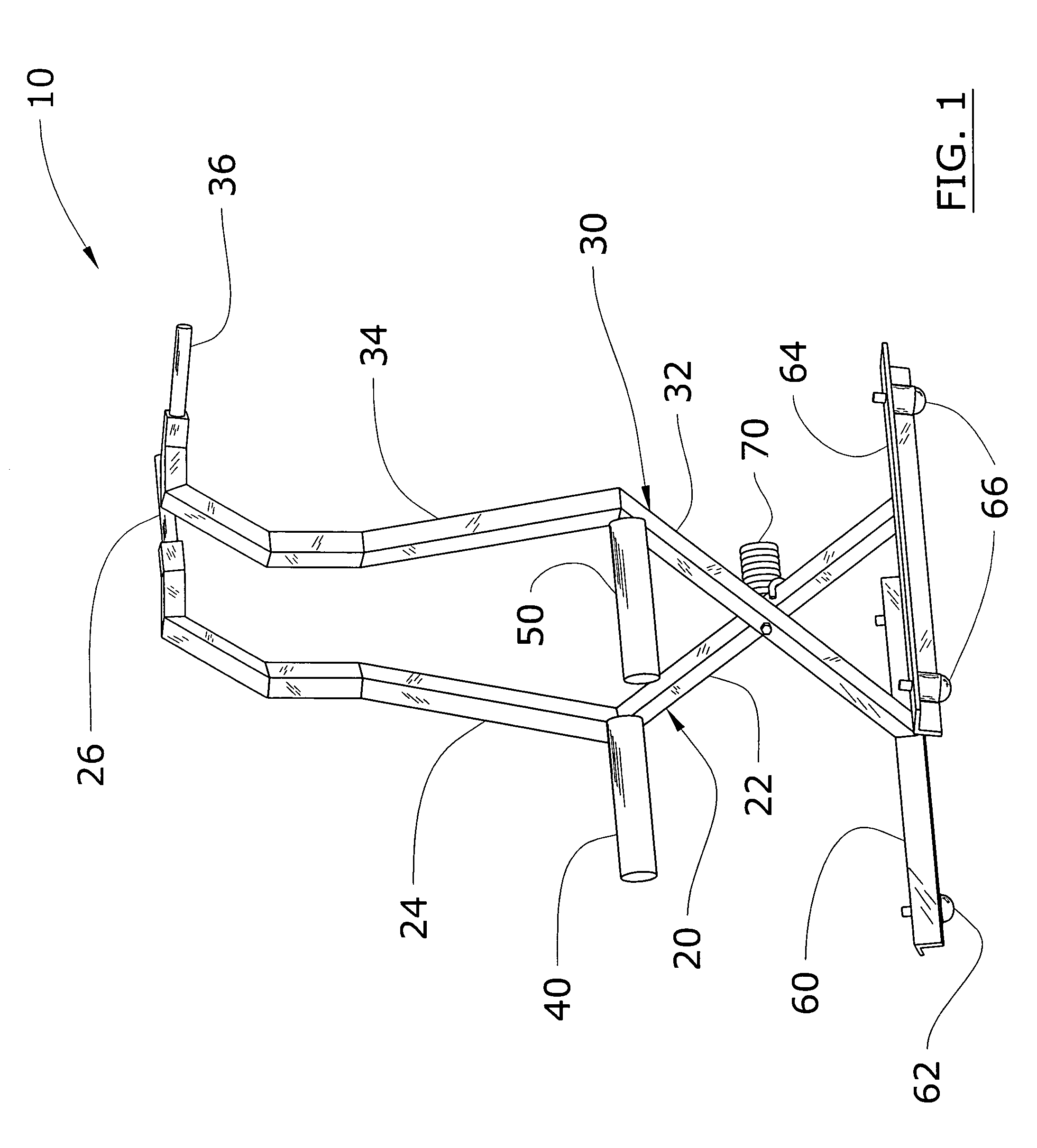
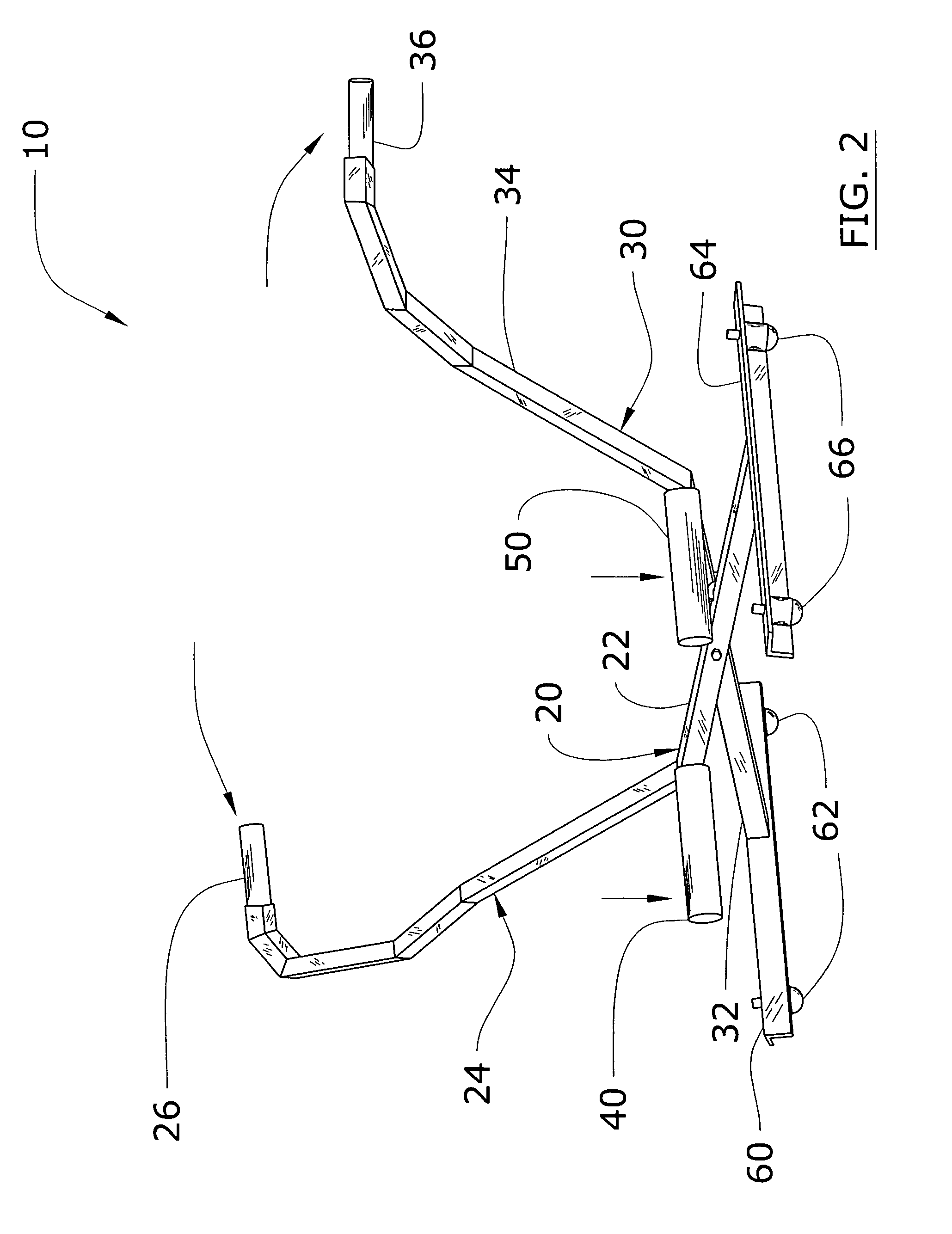
[0034]Turning now descriptively to the drawings, in which similar reference characters denote similar elements throughout the several views, FIGS. 1 through 11 illustrate a wheel lift system 10, which comprises a first arm 20 and a second arm 30 pivotally attached to one another, a plurality of wheels 62, 66 attached to the lower portion of the arms, and a first support 40 and a second support 50 extending from the arms respectively for supporting a wheel and tire 12. A bias member 70 is preferably attached to the arms for providing a bias force that assists in elevating the wheel and tire 12.

B. Arms

[0035]The first arm 20 and the second arm 30 are pivotally attached to one another at a pivot point preferably in a crossing manner forming an X-shaped structure as shown in FIGS. 4 through 11 of the drawings. The pivot point may be at various locations, however the pivot point is preferably at an equal distance from a lower end for each of the arms.

[0036]The first arm 20 is p...


PUM


Abstract

A wheel lift system for efficiently lifting and positioning a wheel and tire onto a wheel hub. The wheel lift system includes a first arm and a second arm pivotally attached to one another, a plurality of caster wheels attached to the lower portion of the arms, and a first support and a second support extending from the arms respectively for supporting a wheel and tire. A bias member is preferably attached to the arms for providing a bias force that assists in elevating the wheel and tire.

Description

CROSS REFERENCE TO RELATED APPLICATIONS[0001]Not applicable to this application.STATEMENT REGARDING FEDERALLY SPONSORED RESEARCH OR DEVELOPMENT[0002]Not applicable to this application.BACKGROUND OF THE INVENTION[0003]1. Field of the Invention[0004]The present invention relates generally to wheel lift devices and more specifically it relates to a wheel lift system for efficiently lifting and positioning a wheel and tire onto a wheel hub.[0005]2. Description of the Related Art[0006]Wheel lift devices have been in use for years. Conventional wheel lift devices are typically comprised of hydraulic / pneumatic bottle jack lifting system that lifts the wheel in position with respect to a wheel hub. Another method of lifting wheels into a desired position with respect to a wheel hub is by manually positioning the wheel with blocks and related objects. Further methods can be found using winches or electric motors that lift a wheel into position. Conventional wheel lift devices are relatively ...

Claims


Application Information

Patent Timeline
IPC IPC(8): B65G7/04
CPCB60B29/002B66F7/0625B66F7/065B66F7/08
Inventor SNOOK, JONATHAN D.
Owner WHEELFLOAT
Why Eureka
Try Eureka