
Wheel lift system

a technology of lifting system and wheel hub, which is applied in the direction of lifting device, wheel mounting apparatus, transportation and packaging, etc., can solve the problems of inconvenient operation of conventional wheel lifting device, inconvenient lifting and positioning of wheel and tire onto wheel hub, and relatively complex and expensive conventional wheel lift devices

Inactive Publication Date: 2011-07-19
WHEELFLOAT
View PDF50 Cites 8 Cited by
  • Summary
  • Abstract
  • Description
  • Claims
  • Application Information

AI Technical Summary

Benefits of technology

"The present invention provides a new wheel lift system that can efficiently lift and position a wheel and tire onto a wheel hub. The system has several advantages over prior art devices, including being compact, lightweight, easily maneuverable, and relatively inexpensive. The system includes a first arm and a second arm pivotally attached to each other, caster wheels attached to the lower portion of the arms, and first and second supports extending from the arms for supporting a wheel and tire. A bias member or bias unit can be attached to the arms for providing a bias force that assists in elevating or maintaining elevation of a wheel and tire. The invention is not limited to the specific details and can be practiced in various ways."

Problems solved by technology

Conventional wheel lift devices are relatively complex and expensive.
In addition, conventional wheel lift devices are relatively cumbersome to operate.
While these devices may be suitable for the particular purpose to which they address, they are not as suitable for efficiently lifting and positioning a wheel and tire onto a wheel hub.

Method used


Image

  • Wheel lift system
  • Wheel lift system
  • Wheel lift system

Examples


first alternative embodiment

F. First Alternative Embodiment

[0061]i. Overview

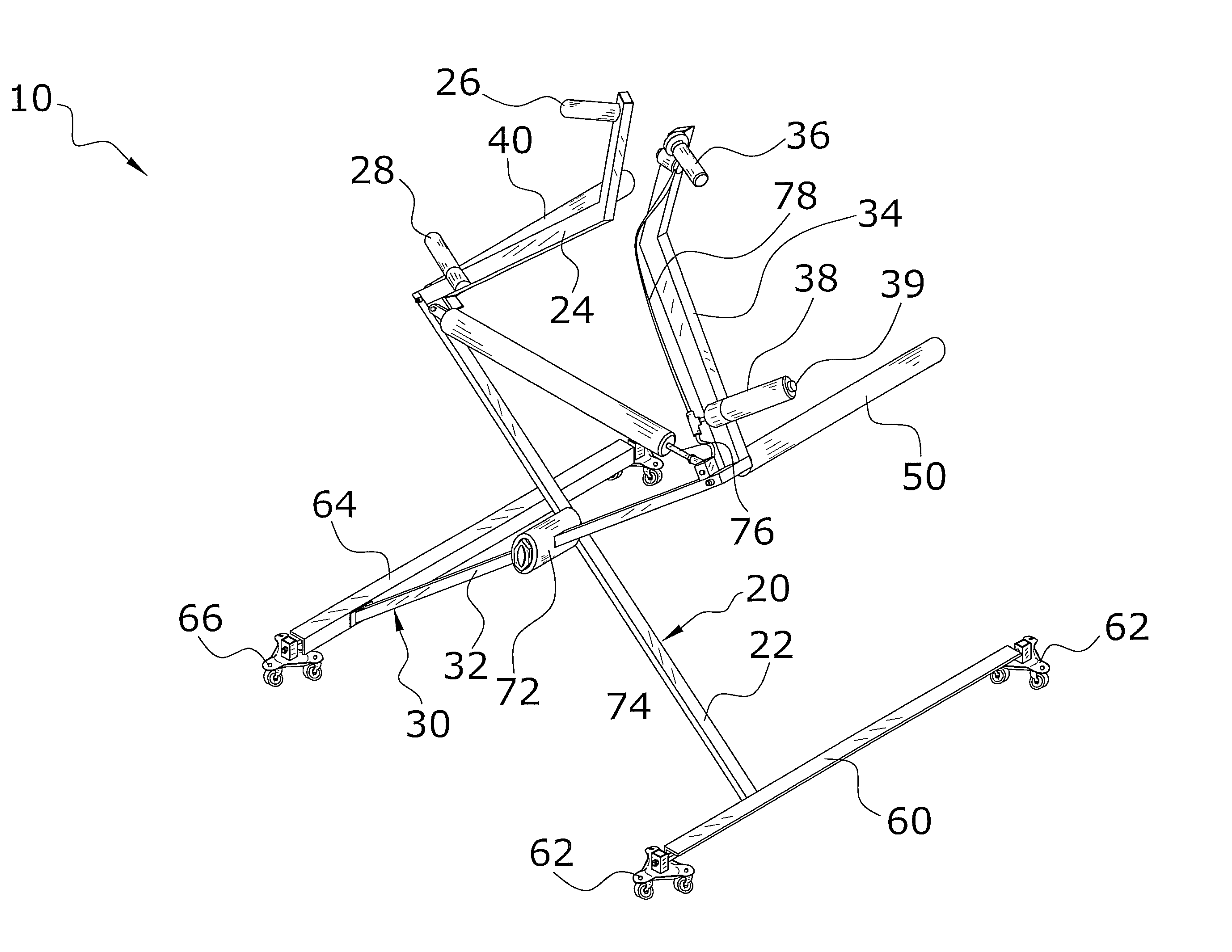
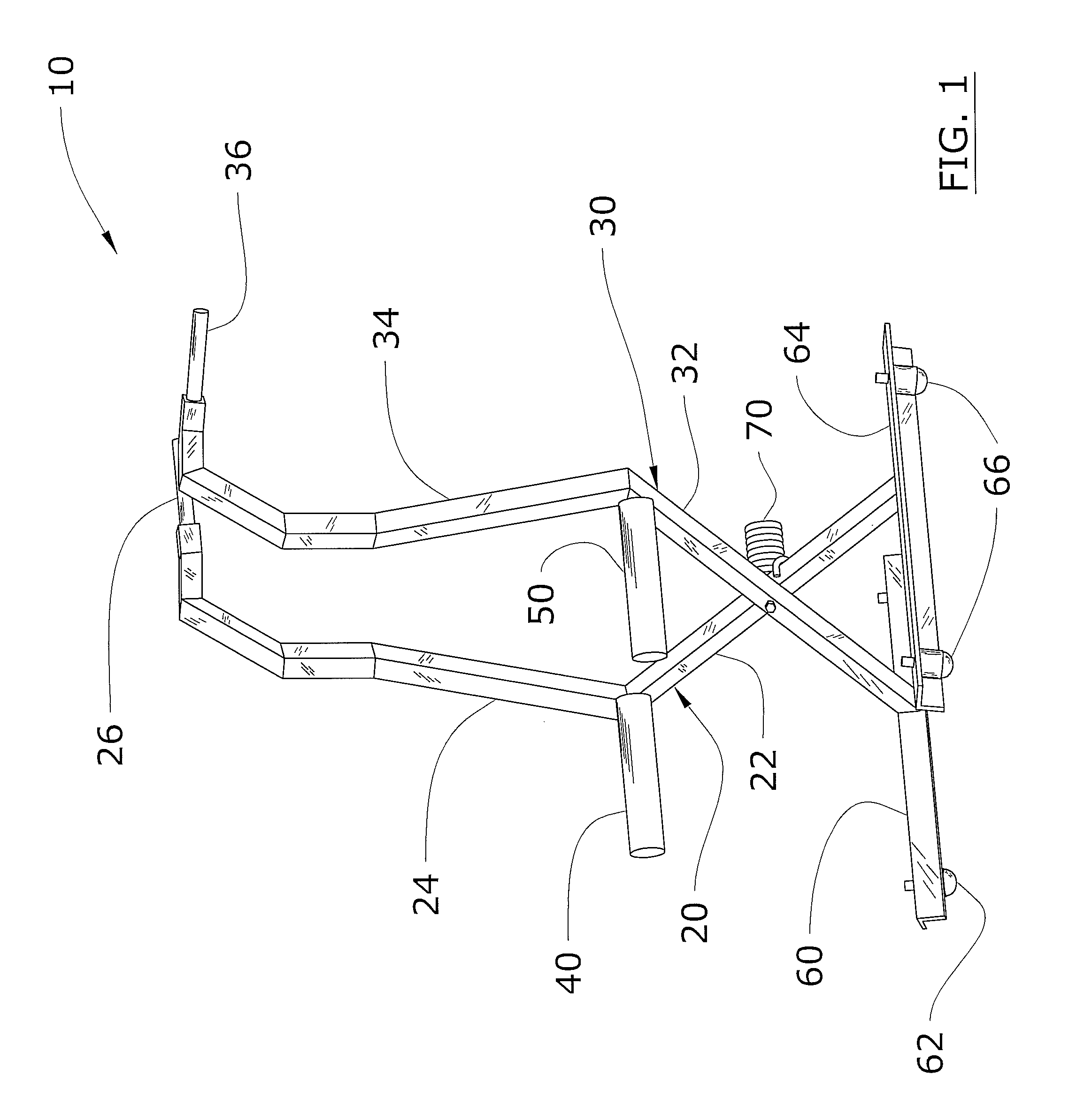
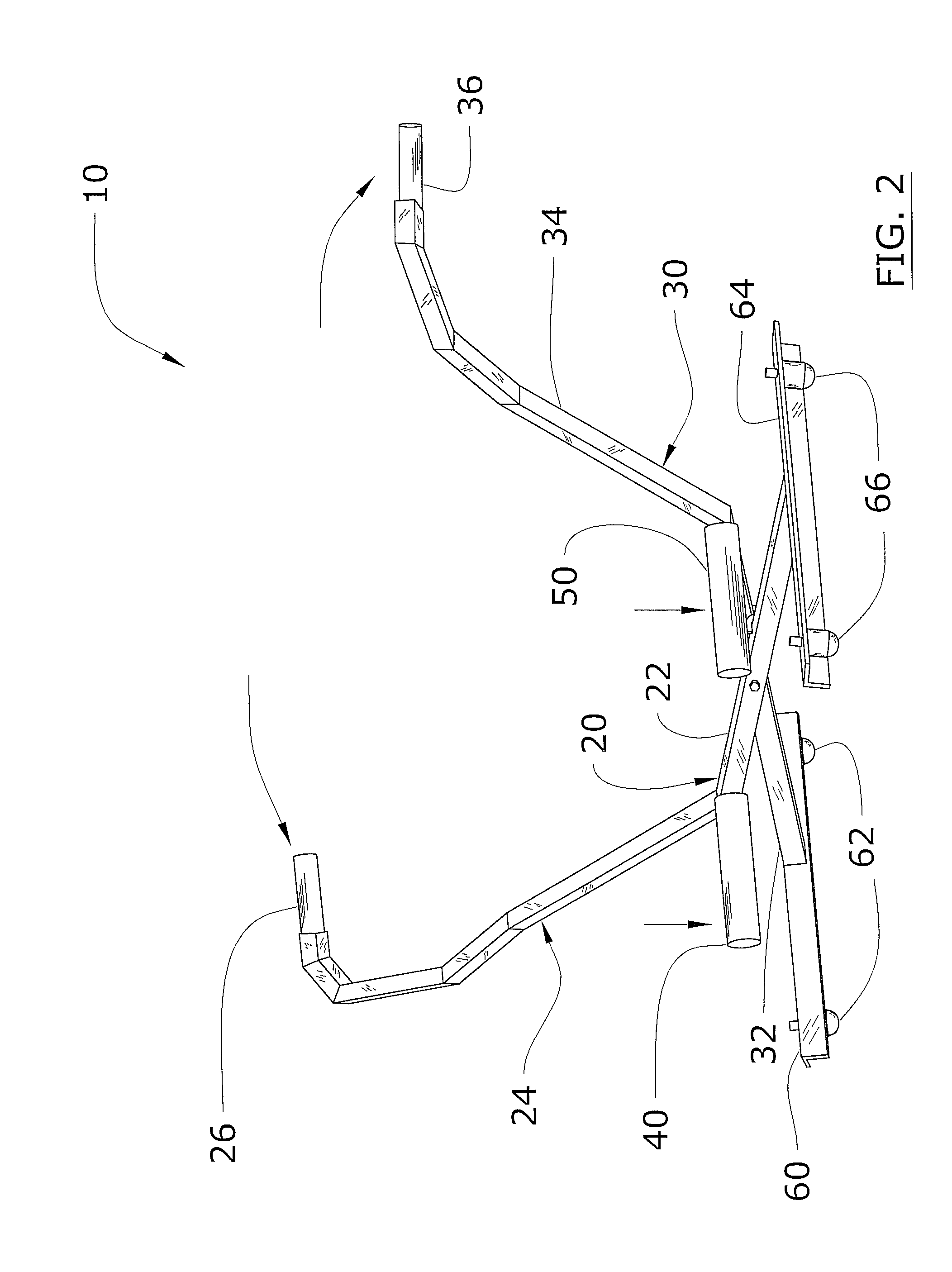
[0062]FIGS. 12 through 17 illustrate a preferred first alternative embodiment of the present invention. More particularly, a wheel lift system 10, which comprises a first arm 20 and a second arm 30 pivotally attached to one another, a plurality of wheels 62, 66 attached to the lower portion of the arms, and a first support 40 and a second support 50 extending from the arms respectively for supporting a wheel and tire 12. A bias unit 74 is attached to the arms for providing a bias force that assists in elevating the wheel and tire 12.

[0063]ii. Arms

[0064]The first arm 20 and the second arm 30 are pivotally attached to one another at a pivot member 72 preferably in a crossing manner forming an X-shaped structure as shown in FIGS. 12 through 16 of the drawings. The pivot member 72 may be at various locations, however the pivot member 72 is preferably at an equal distance from a lower end for each of the arms.

[0065]The first arm 20 is prefe...

second alternative embodiment

G. Second Alternative Embodiment

[0080]FIGS. 18 through 27 illustrate a second alternative embodiment which is discussed further below. The second alternative embodiment utilizes a significant portion of the features in the preferred embodiment and the first alternative embodiment with the following additions or differences.

[0081]i. Foot Lever

[0082]FIGS. 18 through 25 illustrate the foot lever 14 attached to the second upper segment 34. The foot lever 14 is comprised of a vertical portion that is preferably pivotally attached to the second upper segment 34 and a lower horizontal portion that extends outwardly from a lower end of the vertical portion toward the user as best illustrated in FIG. 18 of the drawings. The horizontal portion preferably extends outwardly

[0083]The upper end of the vertical portion of the foot lever 14 is preferably pivotally attached to the second upper segment 34 so that when the user pushes upon the lower horizontal portion with their foot the lower horizon...


PUM


Abstract

A wheel lift system for efficiently lifting and positioning a wheel and tire onto a wheel hub. The wheel lift system includes a first arm and a second arm pivotally attached to one another, a plurality of caster wheels attached to the lower portion of the arms, and a first support and a second support extending from the arms respectively for supporting a wheel and tire. A bias member is preferably attached to the arms for providing a bias force that assists in elevating the wheel and tire. Alternatively, a bias unit may be attached to the arms for providing a bias force that assists in maintaining elevation of a wheel and tire.

Description

CROSS REFERENCE TO RELATED APPLICATIONS[0001]This application is a continuation-in-part of U.S. Pat. No. 7,708,516, formerly patent application Ser. No. 11 / 385,588, filed on Mar. 20, 2006, and issued on May 4, 2010, which is a continuation-in-part of U.S. Pat. No. 7,207,764, formerly patent application Ser. No. 10 / 877,559, filed on Jun. 25, 2004, and issued on Apr. 24, 2007, both of which aforementioned patents are hereby incorporated herein by reference, in their entirety.STATEMENT REGARDING FEDERALLY SPONSORED RESEARCH OR DEVELOPMENT[0002]Not applicable to this application.BACKGROUND OF THE INVENTION[0003]1. Field of the Invention[0004]The present invention relates generally to wheel lift devices and more specifically it relates to a wheel lift system for efficiently lifting and positioning a wheel and tire onto a wheel hub.[0005]2. Description of the Related Art[0006]Wheel lift devices have been in use for years. Conventional wheel lift devices are typically comprised of hydrauli...

Claims


Application Information

Patent Timeline
Patent Type & Authority Patents(United States)
IPC IPC(8): B65G7/04
CPCB60B29/001
Inventor SNOOK, JONATHAN D.FULBRIGHT, THOMAS G.
Owner WHEELFLOAT
Learn More