Air mattress and method of controlling the same

a technology of air mattress and air mattress, which is applied in the field of patient body support technology, can solve the problems of health risk issue for patients and occupying too much healthcare labor resources in conventional procedures, and achieve the effects of reducing healthcare labor resources, reducing patient pain, and facilitating patient head/face rotation

Pending Publication Date: 2022-08-25
APEX MEDICAL CORPORATION
View PDF0 Cites 0 Cited by
  • Summary
  • Abstract
  • Description
  • Claims
  • Application Information

AI Technical Summary

Benefits of technology

[0006]In view of these, the present disclosure provides an air mattress and a method of controlling the same. In some embodiments, the present disclosure is effective in lifting the patient's shoulder-thorax region automatically to provide a face-face-turnover space for the patient and thereby easily turn the patient's head / face with fewer healthcare workers.
[0007]According to some embodiments, an air mattress adapted to be selectively inflated or deflated by an air source, such as air pump controlled by a control system. The air mattress comprises at least one first air cell at a head end of the mattress, a second air cell, a plurality of third air cells and a body-lifting air cell. The second air cell is adjacent to the at least one first air cell. The second air cell comprises a first air chamber, a second air chamber adjacent to the first air chamber, and a structurally-weakened region is enclosed in the second air cell. The third air cells are adjacent to the second air cell. The body-lifting air cell is positioned below the second air cell and at least one of the third air cells. When the air mattress is in use, the air source inflates the body-lifting air cell to lift the second air cell and at least one of the third air cells, such that a vertical distance between the top of the second air cell and the bottom of the air mattress is a first distance, and a vertical distance between the top of the at least one first air cell and the bottom of the air mattress is a second distance, wherein the first distance is greater than the second distance. When the air mattress is in use, the structurally-weakened region has a lower structural strength than any other air cell, and thus the second air cell has a cushioning effect against external forces.
[0008]According to some embodiments, a method of controlling an air mattress is provided. The air mattress comprises at least one first air cell, a second air cell, a plurality of third air cells, and a body-lifting air cell. The air mattress is controlled by a control system when the air mattress is in use. The method comprises controlling an air source to inflate the at least one first air cell, the second air cell and the third air cells; and controlling the air source to inflate the body-lifting air cell and thereby provide a face-face-turnover space. The second air cell supports the shoulder-neck region of the patient, and thus the patient's face can be turned over within the face-face-turnover space. The structurally-weakened region enclosed in the second air cell enables the second air cell to have a cushioning effect against external forces.
[0009]In conclusion, according to some embodiments, the present disclosure is effective in inflating the body-lifting air cell to lift the patient's shoulder-thorax region automatically and to provide a face-turnover space to turn the patient's head / face with fewer healthcare labor resource. In some embodiments, with the patient's shoulder-thorax region being lifted, the structurally-weakened region in the second air cell enables the second air cell to have a cushioning effect against external forces. For example, the pressure exerted by the patient's shoulder-neck region on the second air cell is reduced through the structurally-weakened region while the second air cell supporting the patient's shoulder-neck region. In addition, the risk of hyperextension caused by over extending the prone patient's vertebral column, especially cervical spine, excessively is reduced. In some embodiments, the pressure exerted on the lateral face (especially the ear) of the prone patient is reduced through an orifice of a buffer layer, and thus the chance of developing bedsores on the prone patient's face is also reduced.

Problems solved by technology

The bedsores cause discomfort or even cause a health risk issue to the patients.
However, the aforesaid conventional procedure takes up too much healthcare labor resources.

Method used


Image

  • Air mattress and method of controlling the same
  • Air mattress and method of controlling the same
  • Air mattress and method of controlling the same

Examples


Embodiment Construction

[0020]Terms such as “first” and “second” used herein are used to distinguish between referred components, rather than being used to sort the referred components or limit differences in the referred components or limit the scope of the present invention.

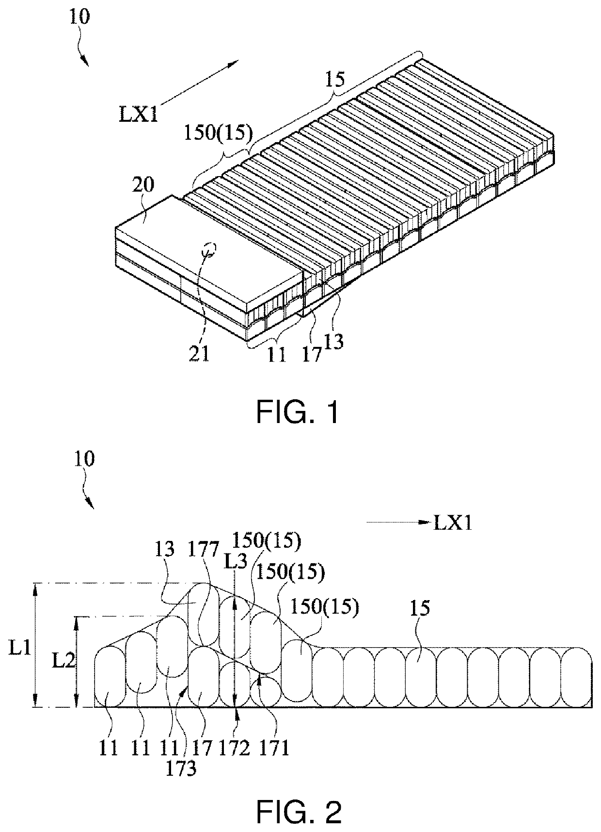
[0021]Referring to FIG. 1, FIG. 1 is a perspective view of an air mattress 10 according to some embodiments of the present disclosure. The air mattress 10 comprises at least one first air cell 11 (herein after at least one head air cell 11), a second air cell 13 (herein after a shoulder-neck air cell 13), a plurality of third air cells 15 (herein after a plurality of torso air cells 15), and a body-lifting air cell 17. The air mattress 10 is adapted to support the body of a patient in a supine or prone position. The patient is face up (that is, the back side of the head of the patient toward to the top side of the air mattress 10) when lying supine on the top side of the air mattress 10, and faces downward (that is, the face of the he...


PUM


Abstract

An air mattress includes a first air cell, a second air cell, a plurality of third air cells, and a body-lifting air cell. The second air cell includes a first air chamber, a second air chamber, and a structurally-weakened region. The body-lifting air cell is below the second air cell and at least one of the third air cells. The body-lifting air cell is inflated by an air source controlled by a control system. When the body-lifting air cell is inflated, a vertical distance between the top of second air cell and the bottom of air mattress is greater than a vertical distance between the top of first air cell and the bottom of air mattress. When the body-lifting air cell is inflated, the second air cell has a lower structural strength than the other air cells to have a cushioning effect against external forces.

Description

CROSS-REFERENCES TO RELATED APPLICATIONS[0001]This application claims the benefit of U.S. provisional application Ser. No. 63 / 153,574, filed on Feb. 25, 2021 and claims the priority of Patent Application No. 110129197 filed in Taiwan, R.O.C. on Aug. 6, 2021. The entirety of the above-mentioned patent applications are hereby incorporated by references herein and made a part of the specification.BACKGROUNDField of the Invention[0002]The present disclosure relates to patient body support technology and, more particularly, to an air mattress and a method of controlling the same.Description of the Prior Art[0003]Bedridden, physically disabled patients are predisposed to development of bedsores for lack of position changing or physical activities. The bedsores cause discomfort or even cause a health risk issue to the patients.[0004]In some circumstances, the patients (especially those with respiratory diseases) have to lie in a prone position to increase the patients' blood oxygen level. ...

Claims


Application Information

Patent Timeline
Patent Type & Authority Applications(United States)
IPC IPC(8): A47C27/10A47C20/04A47C27/08
CPCA47C27/10A47C20/048A47C27/081A61G7/05769A61G7/05776
Inventor CHANG, CHIH KUANGCHEN, YEN CHIEHLIN, SHENG WEIWEI, PO HAN
Owner APEX MEDICAL CORPORATION
Why Eureka
Try Eureka