Ratcheting wrench with quick tightening/loosening functions and fine adjusting functions

a ratcheting wrench and function technology, applied in the field of ratcheting wrenches, can solve the problems of wrenches that wrenches cannot be used in a limited space, and swivel members cannot be used with sockets

Inactive Publication Date: 2005-12-06
HU BOBBY
View PDF262 Cites 46 Cited by
  • Summary
  • Abstract
  • Description
  • Claims
  • Application Information

AI Technical Summary

Benefits of technology

[0007]An object of the present invention is to provide a ratcheting wrench having a drive member that securely receives a fastener-driving member therein and that has a flange allowing a user to quickly turn the drive member together with the fastener-driving member to quickly drive a fastener and allowing the user to finely turn the drive member and the fastener-driving member when desired.
[0008]Another object of the present invention is to provide a ratcheting wrench having a drive member that can be easily manufactured and assembled while providing quick tightening / loosening functions.

Problems solved by technology

However, the pawls are mounted in the box end and thus render a bulky box end such that the wrench cannot be used in a limited space.
Further, the swivel member can only be used with sockets; namely, the swivel member cannot be used with other tools such as screwdrivers.
Further, the swivel member cannot be used to directly drive fasteners.
However, when tightening the fastener 6, the user has to repeatedly move the handle 7 back and forth many times, which is time-consuming and laborious.
However, manufacture and assembly of this ratcheting wrench are troublesome.
More specifically, formation of the annular groove in the inner periphery of the box end and mounting of the C-clip into the annular groove of the box end and the annular groove of the gear wheel are not easy and thus increase the manufacturing cost.
Further, Taiwan Utility Model Publication No. 526807 fails to disclose use of the ratcheting wrench with a screwdriver and thus provides limited functions.

Method used


Image

  • Ratcheting wrench with quick tightening/loosening functions and fine adjusting functions
  • Ratcheting wrench with quick tightening/loosening functions and fine adjusting functions
  • Ratcheting wrench with quick tightening/loosening functions and fine adjusting functions

Examples


first embodiment

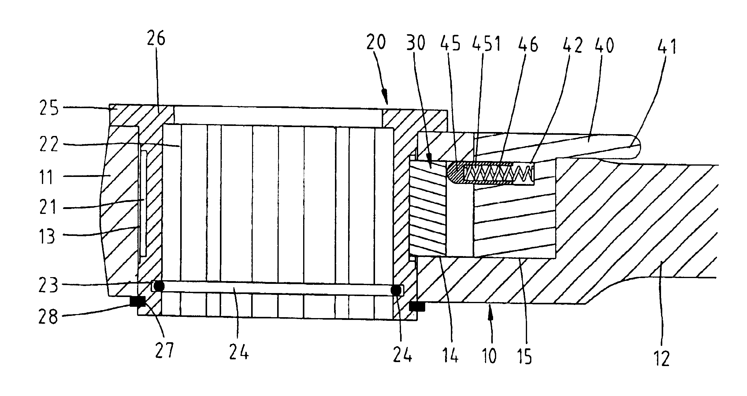
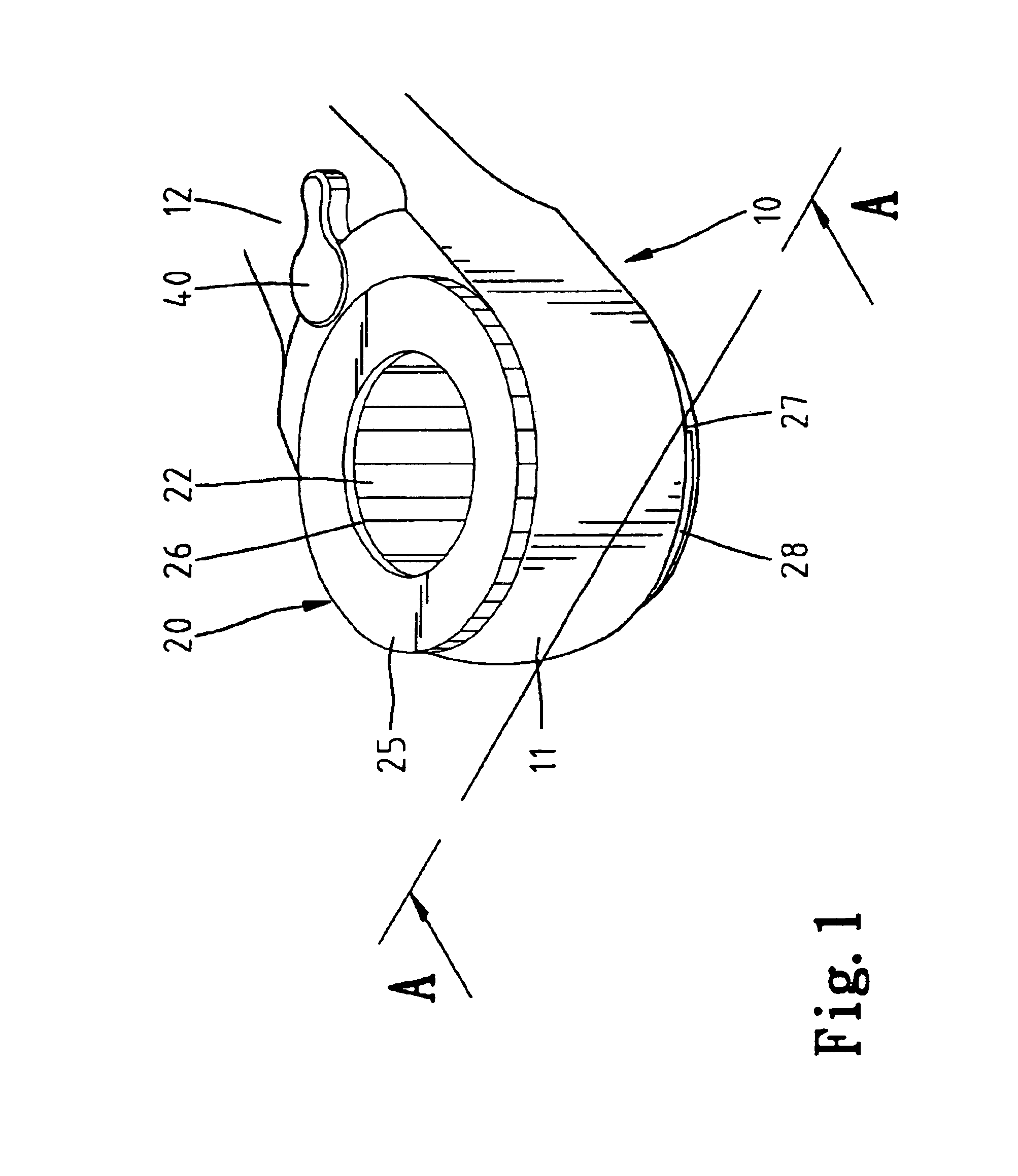
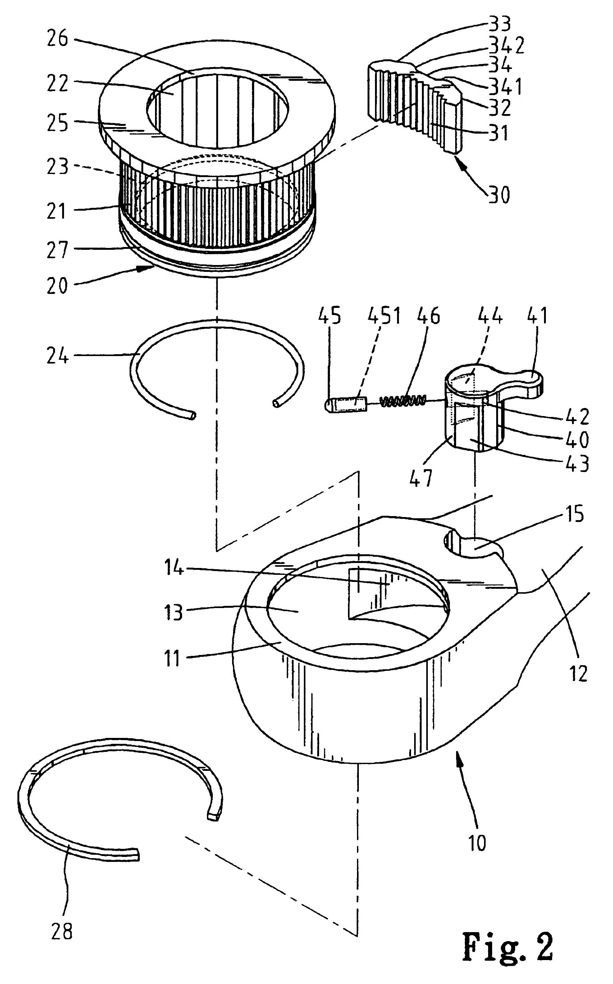
[0035]Referring to FIGS. 1 through 3, a ratcheting wrench in accordance with the present invention is designated by 10 and generally comprises a handle 12 and a head 11 extending from an end of the handle 12. The head 11 is in the form of a box end and includes a hole 13. A compartment 14 is defined in the end of the handle 12 and communicated with the hole 13 of the head 11. In an embodiment of the invention, a ratcheting mechanism is provided in the compartment 14 and includes a pawl 30. An opening 15 is defined in a side (upper side in FIG. 2) of the end of the handle 12 and communicated with the compartment 14.

[0036]A drive member 20 is rotatably held in the hole 13 of the head 11 and includes a first end and a second end. The drive member 20 includes an inner periphery 22 that functions as an engaging portion for engaging with a fastener-driving member (e.g., a screwdriver 50), and a plurality of teeth 21 are defined in an outer periphery of the drive member 20. An annular groo...

second embodiment

[0042]FIGS. 7 through 9 illustrate the ratcheting wrench in accordance with the present invention, wherein like reference numerals designate like elements. In this embodiment, an annular groove 16 is defined in the inner periphery delimiting the hole 13 of the head 11, and a retainer 28′, e.g., a C-clip is partially received in the annular groove 16 of the hole 13 and partially received in the annular groove (now designated by 27′) of the drive member 20′. Further, the flange (now designated by 25′) of the drive member 20′ is formed on the other end of the drive member 20′. It is noted that the drive member 20′ has an upper end that is flush with the upper end face of the head 11. Operation of the wrench of FIGS. 7 through 9 is substantially the same as that of the wrench of FIGS. 1 through 6.

[0043]FIG. 10 illustrates a third embodiment of the ratcheting wrench in accordance with the present invention, wherein like reference numerals designate like elements. Compared to the first em...


PUM


Abstract

A ratcheting wrench includes a handle, a head extending from an end of the handle and having a hole communicated with a compartment in the end of the handle, a drive member rotatably mounted in the hole of the head, and a ratcheting mechanism. The drive member includes an inner periphery for securely holding a fastener-driving member, allowing joint rotation when the drive member is turned. The drive member further includes a flange formed on an end of an outer periphery thereof and located outside the head for manual rotation of the drive member. The ratcheting mechanism is mounted in the compartment of the handle and engaged with the teeth of the drive member, allowing the handle to selectively move in a ratcheting direction for tightening / loosening a fastener and in a free turning direction reverse to the ratcheting direction in which the fastener is not turned.

Description

BACKGROUND OF THE INVENTION[0001]1. Field of the Invention[0002]The present invention relates to a ratcheting wrench having a drive member that securely receives a fastener-driving member therein for driving a fastener such as a screw, bolt, or nut.[0003]2. Description of the Related Art[0004]Ratcheting wrenches have been widely used for tightening / loosening fasteners such as screws, bolts, and nuts, and there are a wide variety of types of ratcheting wrenches. Taiwan Utility Model Publication No. 458012 entitled “Improved Socket Wrench” discloses a wrench including a handle and a head in the form of a box end on an end of the handle. A swivel member is rotatably held in the box end. Two pawls are slidably mounted in the box end and each includes a toothed side for releasably meshing with a toothed inner periphery of the box end. The swivel member includes a protrusion on a central portion of an upper side thereof, thereby forming two recessed portions for respectively receiving the...

Claims


Application Information

Patent Timeline
Patent Type & Authority Patents(United States)
IPC IPC(8): B25B13/46B25B23/00
CPCB25B13/463B25B23/0035
Inventor HU, BOBBY
Owner HU BOBBY
Why Eureka
Try Eureka