Horizontal directional drilling in wells

a directional drilling and well technology, applied in the direction of directional drilling, survey, borehole/well accessories, etc., can solve the problems of destroying the well forever, destroying the well, and halting the whole production process

Inactive Publication Date: 2003-06-17
HORIZONTAL EXPANSION TECH
View PDF82 Cites 48 Cited by
  • Summary
  • Abstract
  • Description
  • Claims
  • Application Information

AI Technical Summary

Benefits of technology

The rotatable working section is attached to the fixed section by a specially designed guide housing and ring gear that facilitates the turning of the turns the rotating section within the well casing. The ring gear converts the rotation of a motor driven transfer bar or drive shaft, turned by a self contained bi-directional variable speed DC motor, into rotation of this section. The DC motor is controlled by an operator at the surface and is powered by a self-contained lithium battery. The rotating section has a rotating vertical bore that passes through the center of the ring gear and into an elbow-shaped channel that changes the direction of the of the flexible shaft and cutter from a vertical entry into a horizontal exit to allow the drilling of holes in the well casing.

Problems solved by technology

It will continue to produce hydrocarbons, until the production drops below a limit that proves to be no longer profitable to continue producing, or it may stop producing altogether.
However, the success of these operations is highly speculative.
In some wells, it may increase the production rate of a well many times over that of its previous record, but in others, they may kill the well forever.
Both Acidizing and Fracturizing are very expensive.
It is very difficult and imperfect to rotate an entire drill string, so that the exit hole of the shoe, which is located at the bottom of the drill string, is pointing exactly in the desired direction.

Method used


Image

  • Horizontal directional drilling in wells
  • Horizontal directional drilling in wells
  • Horizontal directional drilling in wells

Examples


Embodiment Construction

The entire contents of U.S. Provisional Patent Application No. 60 / 182,932, filed Feb. 16, 2000 and U.S. Provisional Patent Application No. 60 / 199,212, filed Apr. 24, 2000 are incorporated herein by reference.

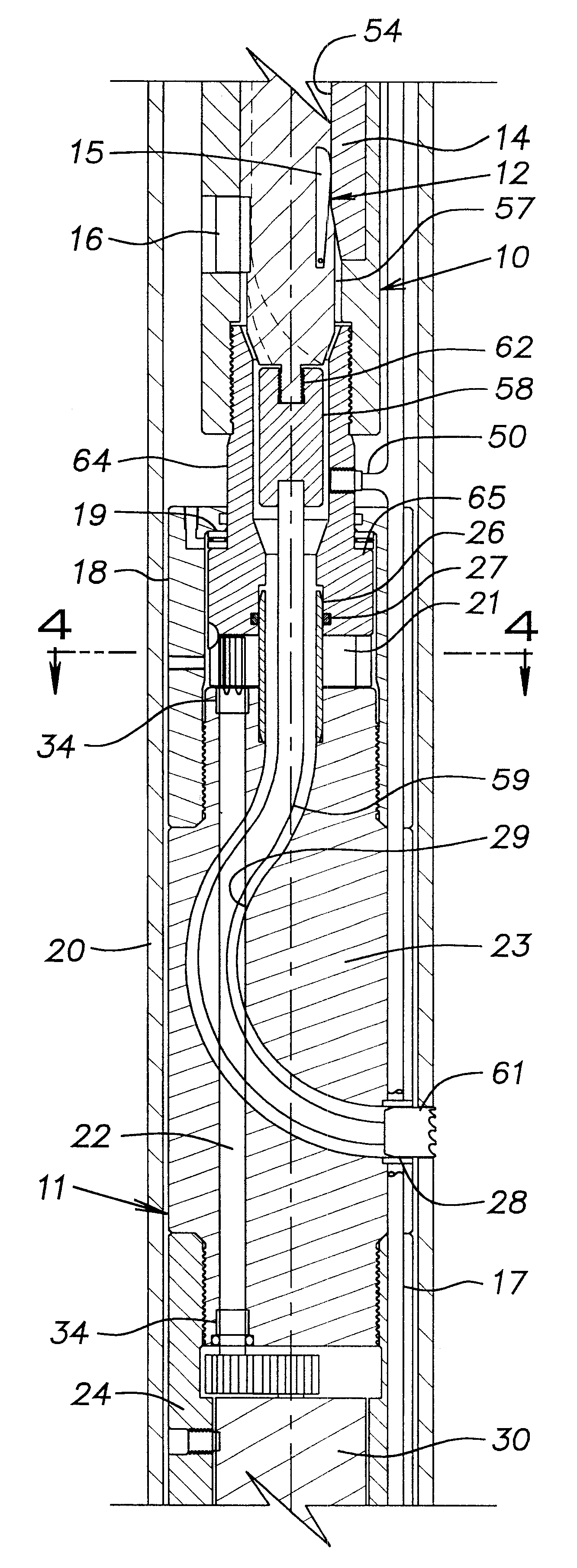
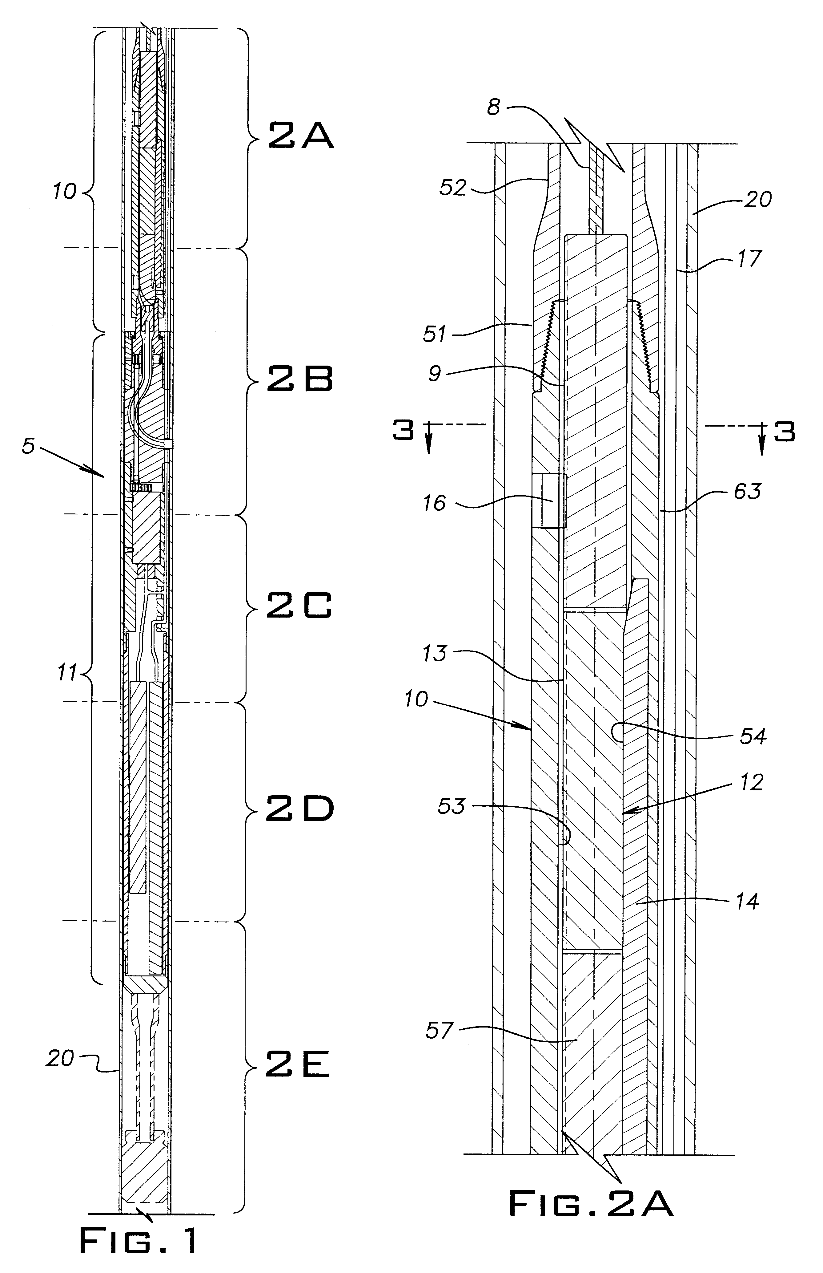
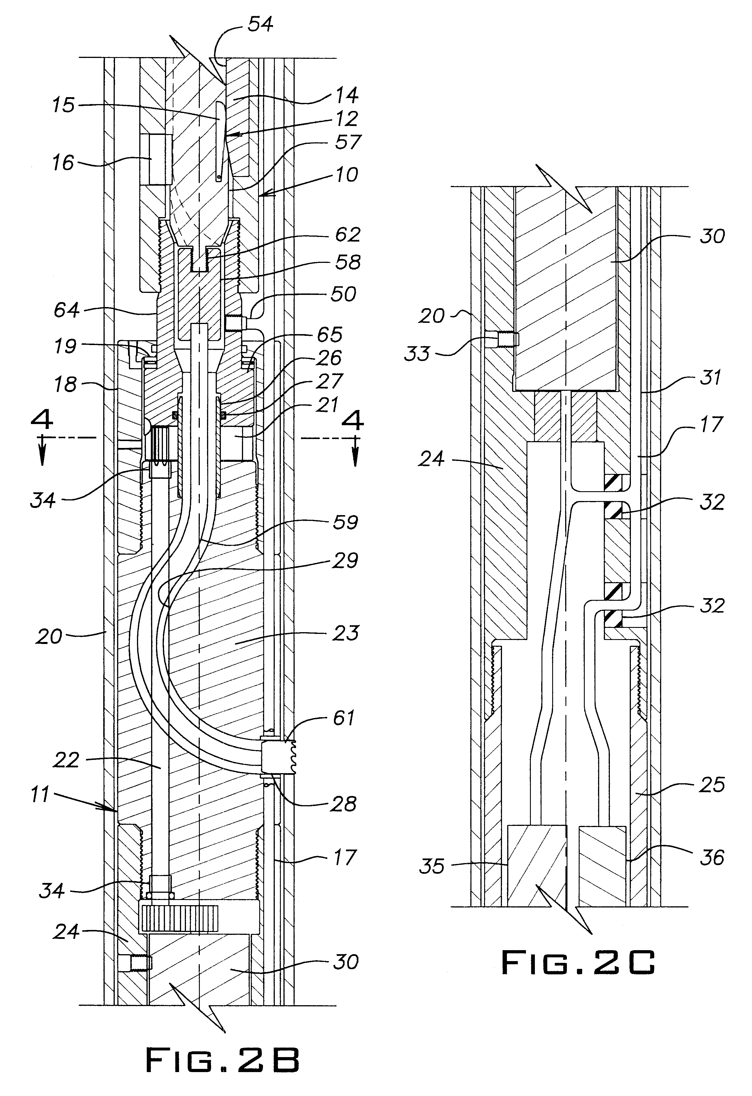
FIG. 1 and FIGS. 2A through 2E schematically illustrate components of a cylindrical shoe assembly 5 capable of horizontally drilling into vertical well casings 20 and boring into hydrocarbon payzones in oil and gas wells. It will be understood that the invention has other applications from the following description, such as employing a coring bit that would core into the side of the well casing 20 and part of the surrounding formation to determine the casing condition and the composition of the surrounding formation, using a milling tool to cut the well casing 20 in two, employing a series or battery of small shaped charges to produce holes in the side of the casing 20 or to use a video camera or sonar device to locate and determine interior defects and imperfections in the well...


PUM


Abstract

A method and apparatus for horizontally drilling in wells utilizing a shoe assembly at the down hole end of upset tubing. The shoe assembly includes a fixed section and a rotatable section suspended below the fixed section. An electric motor and associated batteries and a gyroscope carried on the rotatable section enable an operator on the surface to selectively rotate and position the rotatable section to any desired angular location for drilling a hole in the well casing. After one or more holes have been cut in the casing, a drill assembly can be removed from the upset tubing and be replaced by a high pressure blaster nozzle to bore into the formation zones. The gyroscope enables the operator to accurately position the rotatable section to the same locations at which the holes have been cut. The drill assembly includes an electric motor with an associated battery, flexible drive shaft, and a hole saw.

Description

BACKGROUND OF INVENTIONThe invention relates to not only new wells, but also to revitalizing preexisting vertical and horizontal oil and gas vertical wells that have been depleted or are no longer profitable, by improving the porosities of the wells' payzone formations. This is accomplished by providing a micro channel through the already existing casing, and out into the formation.PRIOR ARTAfter a well has been drilled, completed, and brought on-line for production, it may produce oil and gas for an unknown period of time. It will continue to produce hydrocarbons, until the production drops below a limit that proves to be no longer profitable to continue producing, or it may stop producing altogether. When this happens, the well is either abandoned or stimulated in a proven and acceptable process. Two of these processes are called Acidizing and Fracturizing. Acidizing uses an acid to eat away a channel in the formation thus allowing the hydrocarbons an easier access back to the wel...

Claims


Application Information

Patent Timeline
Patent Type & Authority Patents(United States)
IPC IPC(8): E21B29/00E21B7/04E21B7/06E21B29/06E21B47/02E21B47/024E21B7/08
CPCE21B7/061E21B49/06E21B47/024E21B29/06
Inventor MAZOROW, HENRY B.BLAIR, PARIS E.SANFELICE, CHRIS
Owner HORIZONTAL EXPANSION TECH
Why Eureka
Try Eureka