Backlight assembly using the same and liquid crystal display device

a technology of liquid crystal display and backlight assembly, which is applied in the direction of lighting and heating apparatus, mechanical equipment, instruments, etc., can solve the problems of optical sheet being easily wrinkled, display quality deterioration, image information not being normally displayed on the screen, etc., and achieve the effect of preventing the optical sheet from being wrinkled or scratched

Inactive Publication Date: 2007-05-29
SAMSUNG DISPLAY CO LTD
View PDF7 Cites 42 Cited by
  • Summary
  • Abstract
  • Description
  • Claims
  • Application Information

AI Technical Summary

Benefits of technology

[0012]Accordingly, the present invention has been devised to solve the foregoing problems of the conventional art, and it is a first object of the present invention to provide a backlight assembly capable of preventing an optical sheet from being wrinkled or scratched with heat or impact applied to the optical sheet.
[0013]It is a second object of the present invention to provide an LCD device capable of preventing an optical sheet from being wrinkled or scratched with heat or impact applied to the optical sheet.
[0016]According to the present invention, the optical member is adhered to the receiving container using the elastic adhesive member that is flexible corresponding to deformation of the optical member with heat and absorbs impact applied to the LCD device, thereby preventing the optical sheet from being wrinkled or scratched.

Problems solved by technology

Particularly, in case that the optical part securely fixed to the frame by double sided tape is expanded, the optical part may be easily wrinkled because there is no extra space in the frame of the LCD device.
As a result, image information may not be normally displayed on a screen.
However, in case of fixing the optical part to the frame such that it may be moved in the frame, the optical part may collide with the liquid crystal controlling part adjacent to the optical part when impact is applied to the frame of the LCD device.
As a result, the optical part and the liquid crystal controlling part may be fatally damaged by scratch therebetween so that display quality is deteriorated.

Method used


Image

  • Backlight assembly using the same and liquid crystal display device
  • Backlight assembly using the same and liquid crystal display device
  • Backlight assembly using the same and liquid crystal display device

Examples


Embodiment Construction

[0029]

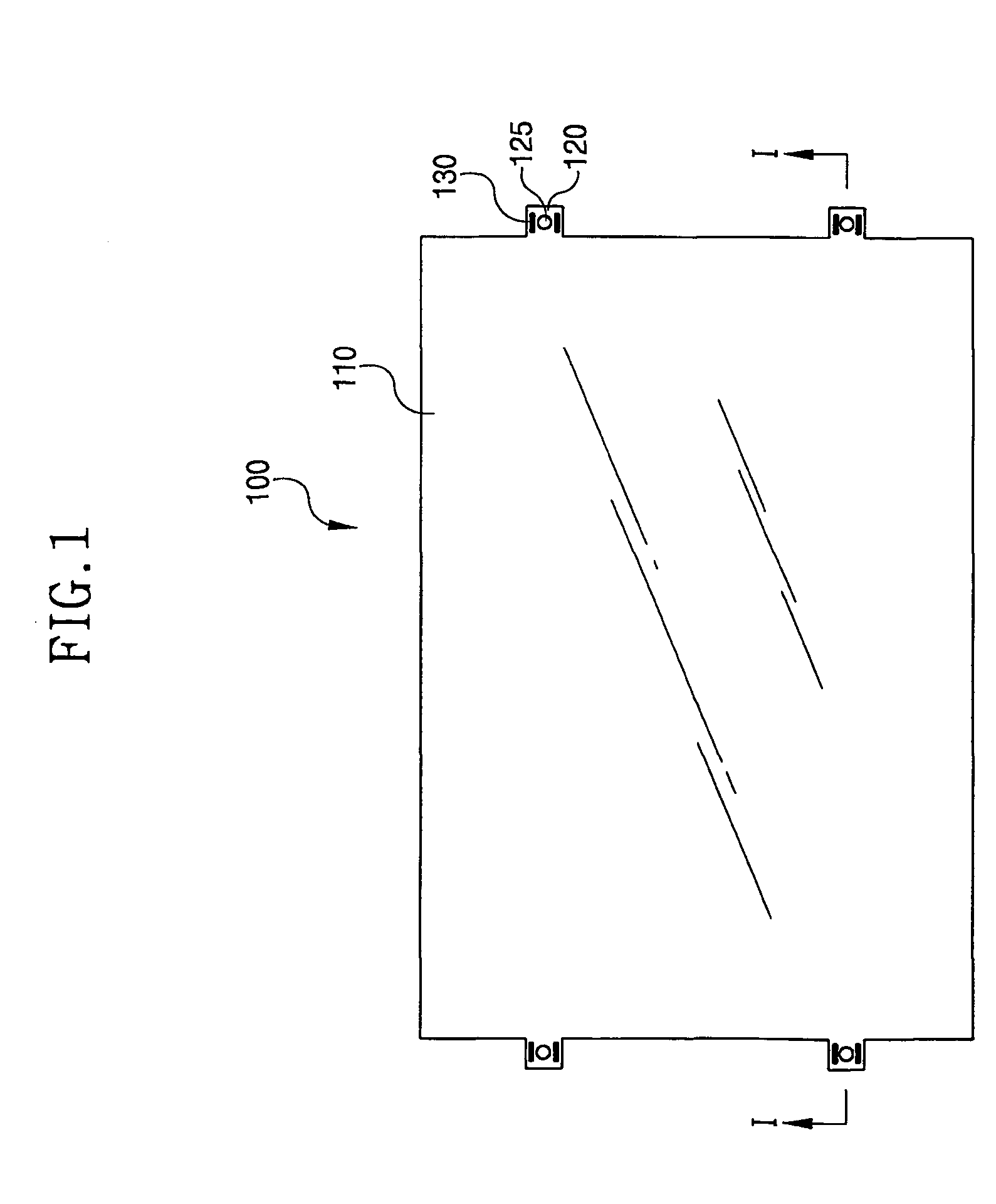
[0030]FIG. 1 is a plane view showing an optical sheet according to a first exemplary embodiment of the present invention.

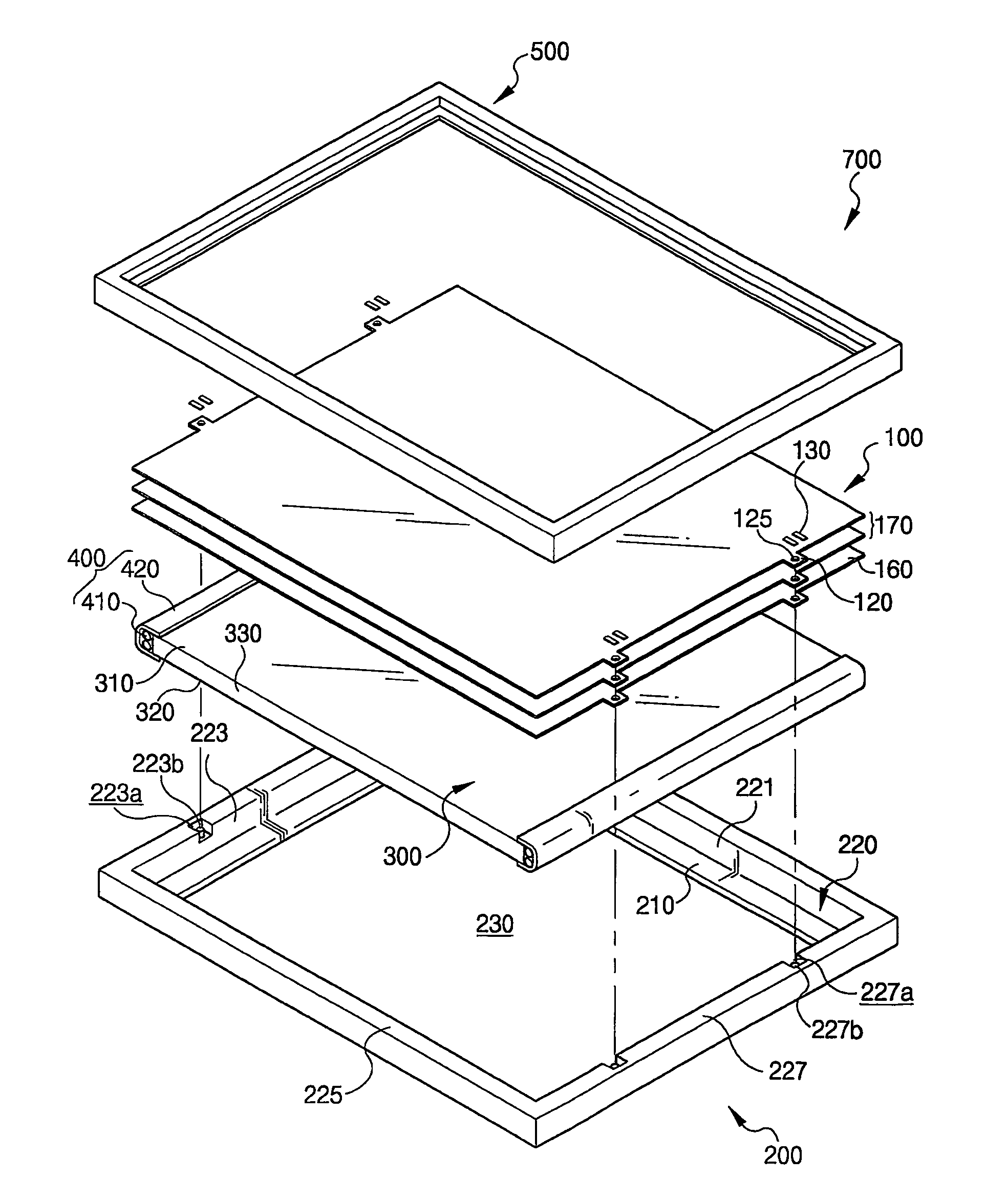
[0031]Referring to FIG. 1, an optical sheet 100 is disposed between a light source and an LCD panel. The optical sheet 100 controls optical properties of light emitted from the light source and supplies the light to the LCD panel. The LCD panel can display image information having superior image quality by using functions of the optical sheet 100 as described above.

[0032]Display devices using liquid crystal, in general, employ at least one optical sheet 100 having various optical characteristics needed to display image information.

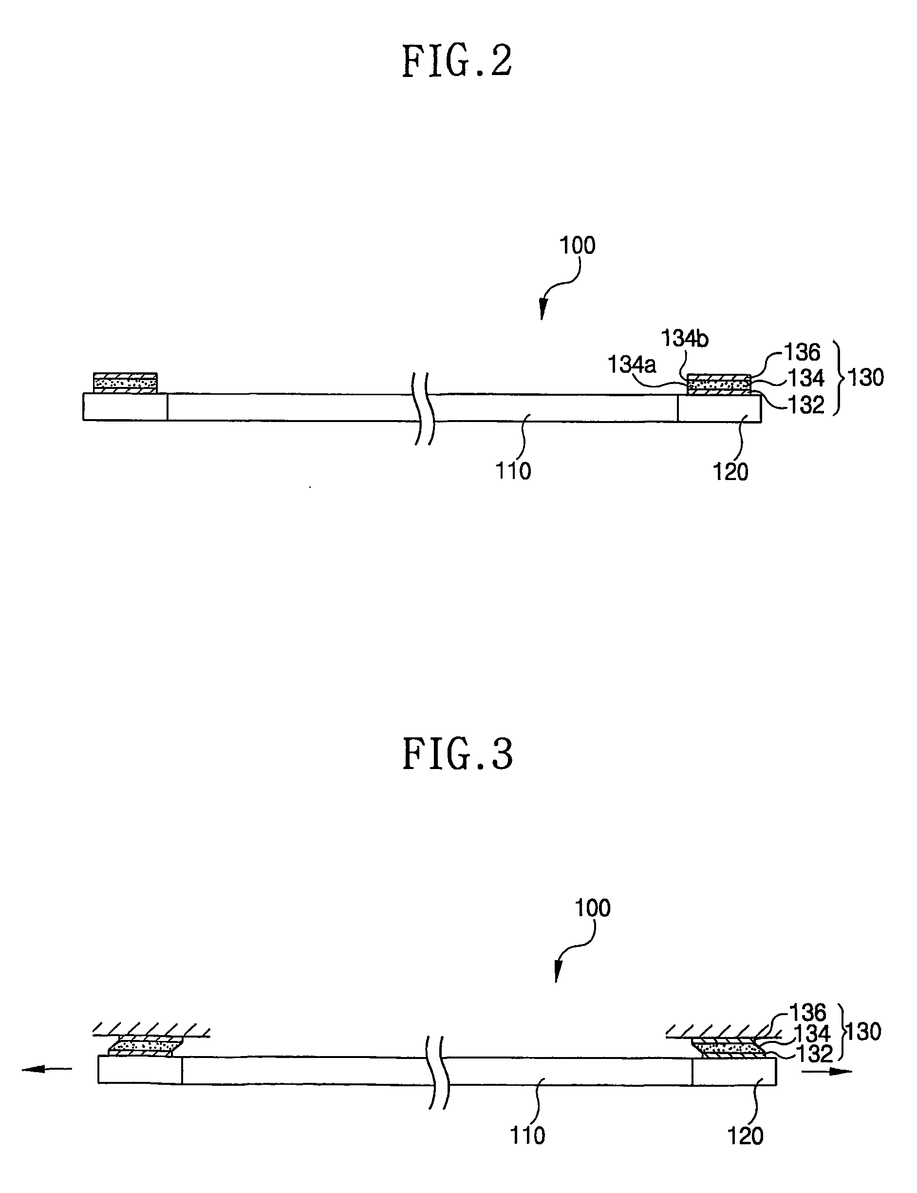
[0033]The optical sheet 100 is formed in a shape of thin plate so as to minimize thickness of an LCD device. The optical sheet 100 has a size corresponding to that of the LCD panel and a shape similar to that of the LCD panel.

[0034]As shown in FIG. 1, the optical sheet 100 has a rectangular shape. The optical sheet 100 according to...


PUM

PropertyMeasurementUnit
brightnessaaaaaaaaaa
optical characteristicsaaaaaaaaaa
lengthaaaaaaaaaa

Abstract

There are provided a backlight assembly (700) and an LCD device (1000) using the same. The backlight assembly (700) has an optical sheet (100) for improving light efficiency and optical properties thereof and an elastic adhesive member (130) disposed on the optical sheet (100). When the optical sheet (100) deforms with heat, the elastic adhesive member (130) may be expanded or contracted corresponding to deformation of the optical sheet (100) and absorb impact applied to LCD device. Accordingly, the backlight assembly (700) may prevent the optical sheet (100) from being wrinkled or scratched, thereby preventing display quality of the LCD device from being deteriorated.

Description

TECHNICAL FIELD[0001]The present invention relates to a backlight assembly and a liquid crystal display (LCD) device, and more particularly to a backlight assembly capable of preventing an optical sheet from being wrinkled or scratched with heat or impact applied to the optical sheet, thereby preventing display quality from being deteriorated and LCD device having the same.BACKGROUND ART[0002]In general, an LCD device displays image information using liquid crystal. In order to display image information, an LCD device includes a light supplying part that generates light needed to display image information, an optical part that allows light supplied from the light supplying part to have uniform brightness and a liquid crystal controlling part that controls liquid crystal.[0003]The LCD device employs a CCFL (Cold Cathode Fluorescent Lamp) having characteristics, for example, such as a long life, a white light and a small amount of heat generation as a light supplying part.[0004]The op...

Claims


Application Information

Patent Timeline
Patent Type & Authority Patents(United States)
IPC IPC(8): G02F1/1333F21V8/00F21Y103/00G02F1/13G02F1/1335G02F1/13357
CPCG02B6/0088G02F1/133606G02F1/133615G02F2201/503G02F2201/54G02F1/1335
Inventor CHA, GUY-HOPARK, JONG-DAECHANG, SE-INLEE, SEOK-WON
Owner SAMSUNG DISPLAY CO LTD
Why Eureka
Try Eureka