Modified fishhook for catch and release applications

a technology for fishhooks and catch and release, applied in the field of fishhooks, can solve the problems of permanent harm of fish, potent infection, and potentially interfering with fish's normal feeding habits, and achieve the effect of minimal damage or harm, not unduly damaged or harm

a technology for fishhooks and catch and release, applied in the field of fishhooks, can solve the problems of permanent harm of fish, potent infection, and potentially interfering with fish's normal feeding habits, and achieve the effect of minimal damage or harm, not unduly damaged or harm

US7225582B2Inactive Publication Date: 2007-06-05SHAY ROBERT

Image

  • Modified fishhook for catch and release applications
  • Modified fishhook for catch and release applications
  • Modified fishhook for catch and release applications

Examples


Embodiment Construction

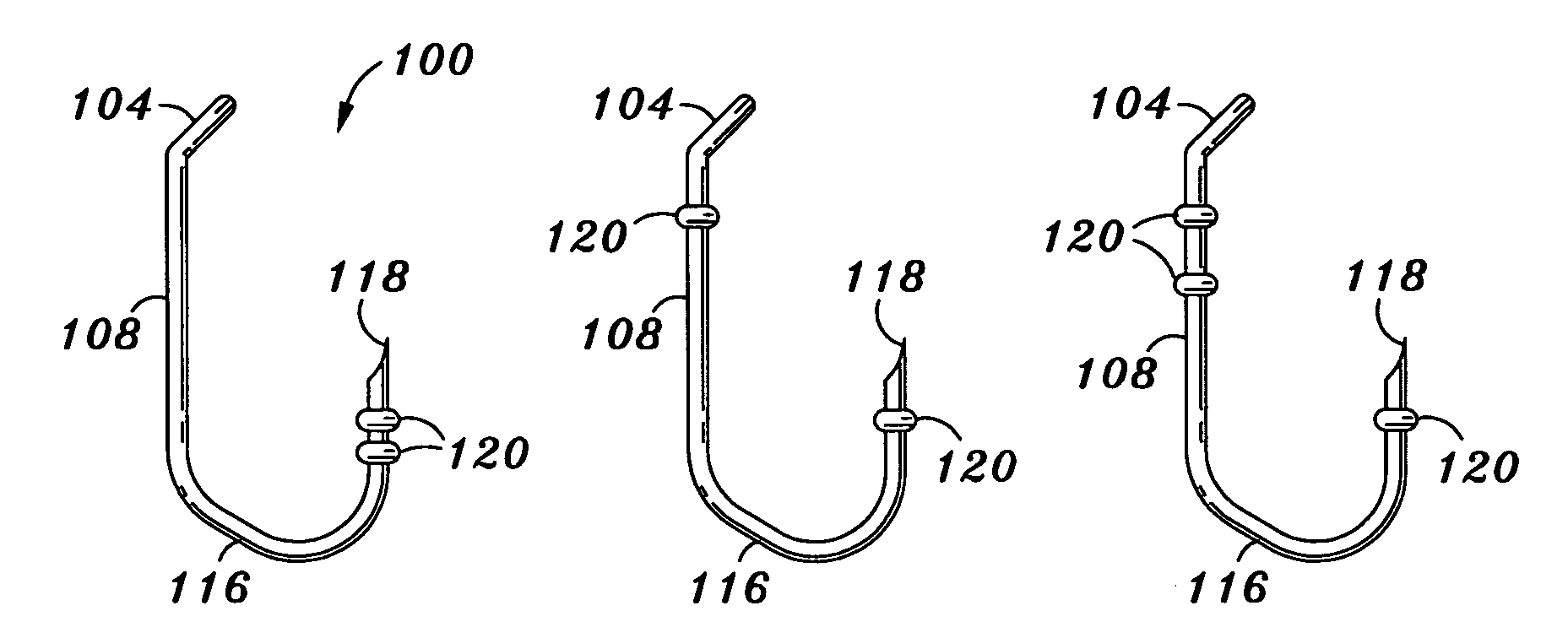
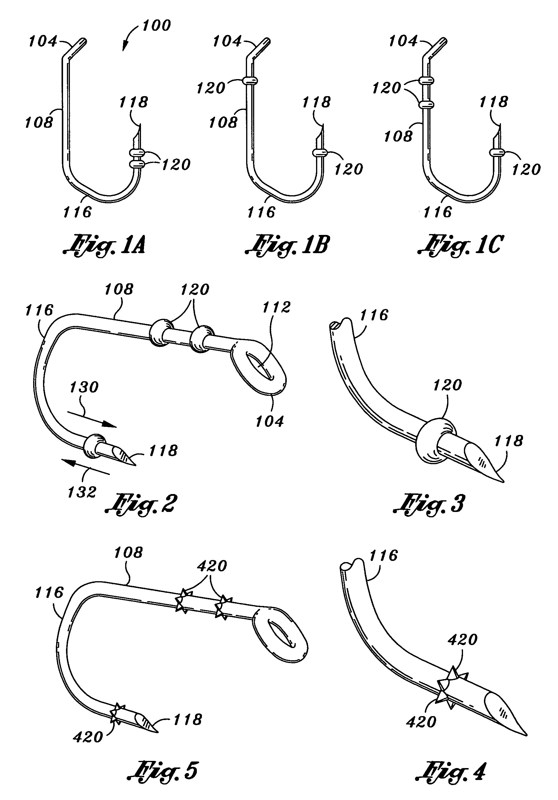
[0024]FIGS. 1A, 1B, and 1C, FIG. 2 and FIG. 3 illustrate side pan views and perspective views of an exemplary fishhook 100 configured according to the method and apparatus disclosed herein. As shown, a fishhook comprises an eye 104 at a first connected or formed from a shank 108. In this exemplary embodiment the eye 104 forms an opening 112 configured to accept a fishing line, in the case of direct tied hook, a swivel, or other device or element that serves as an interface between the hook and the fishing line or leader. The eye 104 and its associated method of manufacture, assembly, location, composition, and the like may comprise any eye configuration known in the art or developed in the future. The eye 104 is generally understood by one of ordinary skill in the art of fishhooks and as such the eye is not described in detail herein.

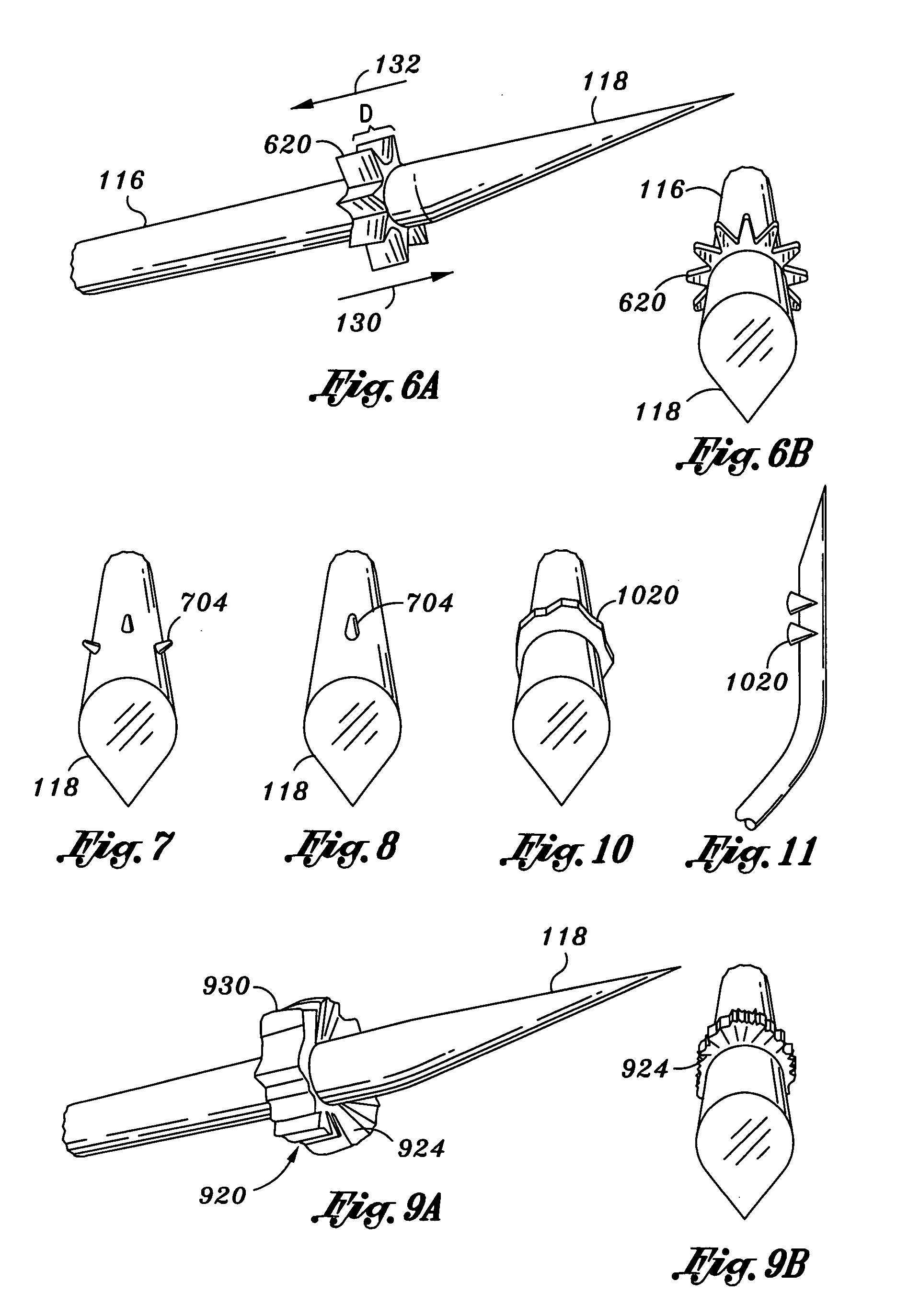
[0025]The shank 108 comprises a generally straight or curved section that separates the eye 104 from a curved portion referred to herein as a bend 116....


PUM


Abstract

A fishhook for use in catch and release application or when it is desired to inflict minimal damage to the fish. The hook comprises an eye, shank, bend and point. One or more dogs are located on the bend, the shank, or both. The dogs comprise non-barbed raised surfaces or structures. In one or more various embodiments the dogs comprise toroidal shaped raised surfaces, star shaped raised surfaces, raised surfaces with rough outer edges, raised surfaces having inwardly sloping side surfaces, crescent shaped raised surfaces, raised surfaces comprising nubs or cone shapes, or any combination thereof. One or more dogs may also be located on the shank.

Description

FIELD OF THE INVENTION[0001]The invention relates to fishing, and in particular to an improved fishhook.RELATED ART[0002]Fishing is a popular activity for sportsmen, outdoor recreationists, and environmentalists. While many fishermen fish to obtain a source of food, a growing segment of the fishing population perform catch and release, whereby once a fish is caught and landed, the fish is subsequently released back into the water. This maintains the fish stock for future outings and future generations of fishermen. Furthermore, catch and release may be considered to be a more humane means by which to enjoy fishing because the fish is not permanently harmed. Moreover, catch and release is becoming increasingly more popular as more and more people compete for the same resources offered by a limited number of streams and lakes.[0003]Prior art fishhooks and lures share a common characteristic by having a generally sharp and pointed barb located near the point of the bend, i.e. hooked po...

Claims


Application Information

Patent Timeline
05 Jun 2007
Publication
US7225582B2
IPC
A01K83/00; A01K83/04
CPC
A01K83/00; A01K83/04
Inventors
SHAY, ROBERT