Plain bearing

a bearing and bearing technology, applied in the direction of sliding contact bearings, crankshaft bearings, mechanical equipment, etc., can solve the problems of local contact between the end of the plain bearing halves and the shaft, drop in and lowering oil pressure in the lubricating system

Active Publication Date: 2007-06-26
DAIDO METAL CO LTD
View PDF11 Cites 36 Cited by
  • Summary
  • Abstract
  • Description
  • Claims
  • Application Information

AI Technical Summary

Problems solved by technology

On the other hand, in the case of the plain bearing comprising plain bearing halves described above, when plain bearing halves are mounted in the housing, there are some cases where misalignment is generated at joints of ends of plain bearing halves, or deformation is caused in the vicinity of the joints of the ends of the plain bearing halves if crush height is too high.
In such plain bearings in which crush relieves are formed, there is a problem that the lubrication oil supplied to the oil grooves flow into the crush relieves to leak out from the crush relieves in an axial direction, so that oil pressure in a lubricating system is lowered.
By the way, the plain bearing disclosed in JP-Y2-61-573 is not formed with crush relieves and so free from the problem that leakage of a lubrication oil due to the provision of the crush relieves results a drop in oil pressure in the lubricating system, but involves a problem that local contacts are resulted between ends of plain bearing halves and the shaft.

Method used


Image

  • Plain bearing
  • Plain bearing
  • Plain bearing

Examples


Embodiment Construction

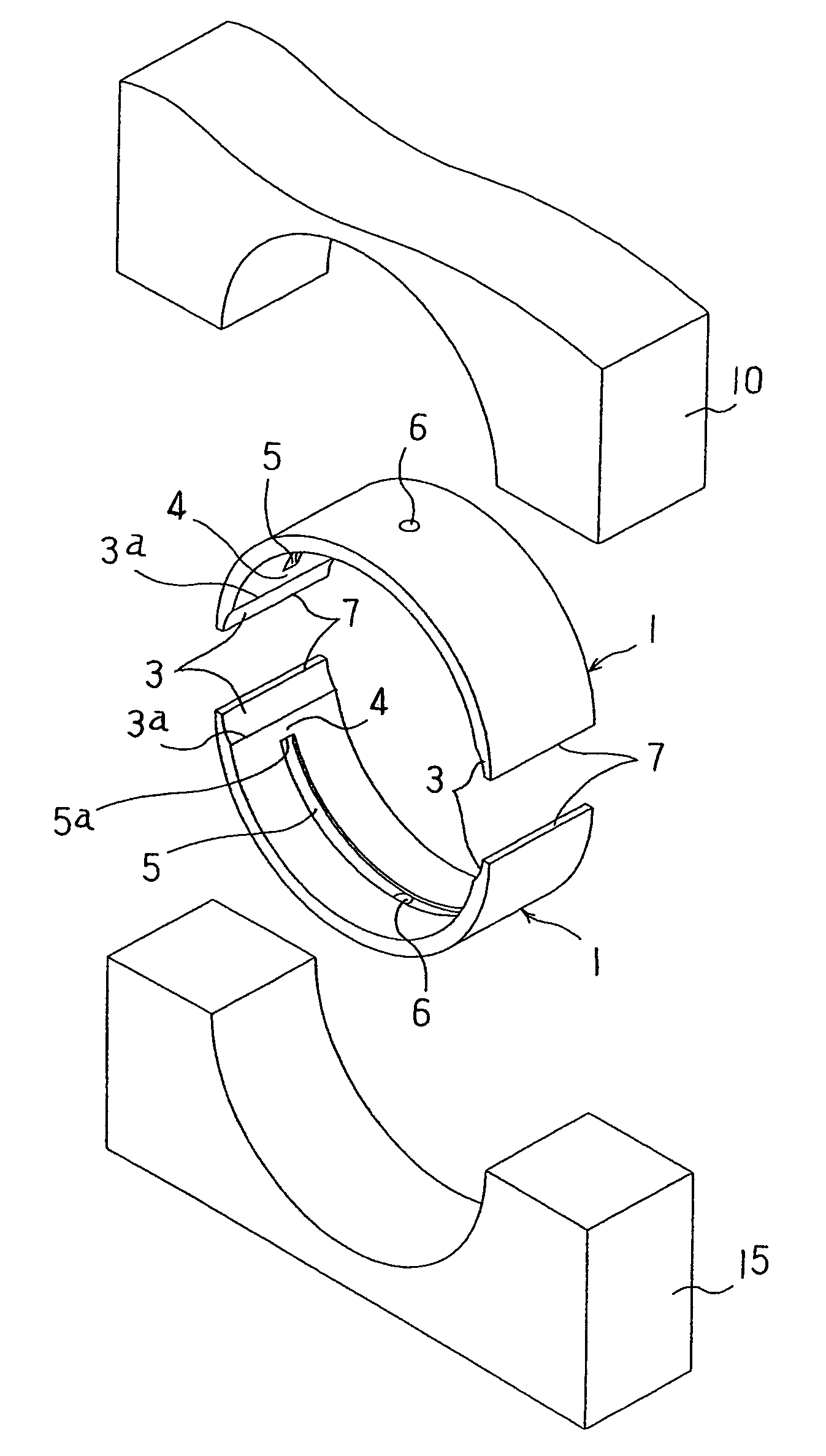
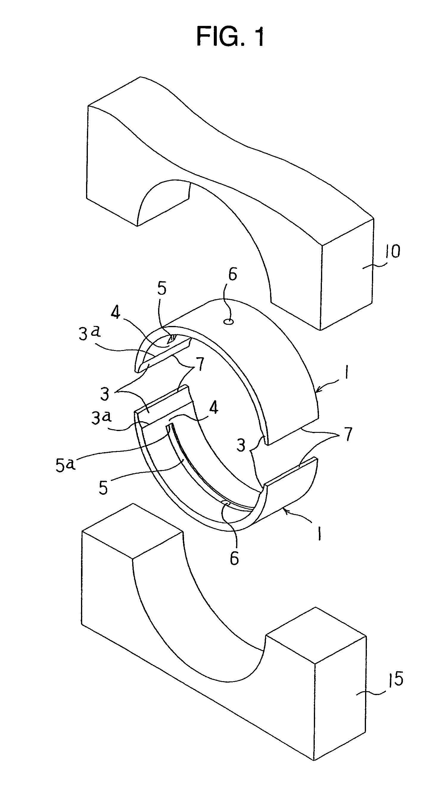
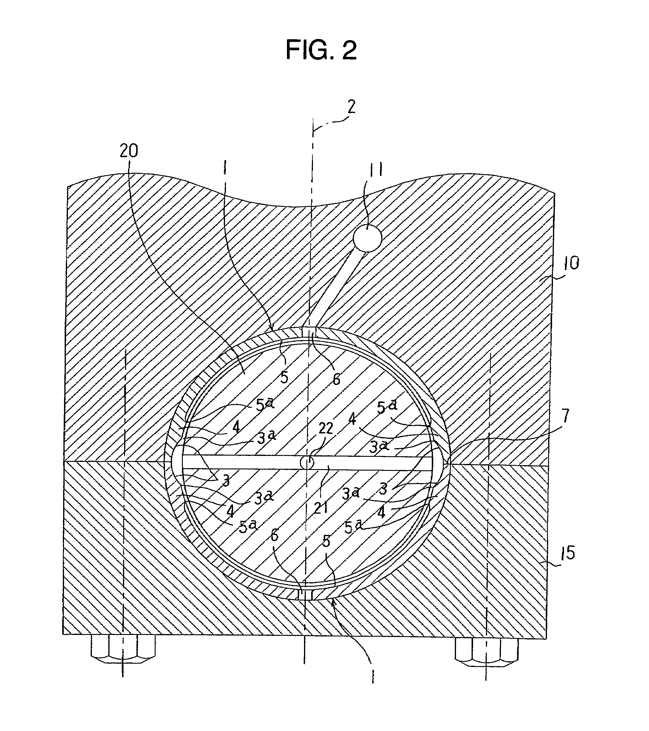
[0016]Embodiments of the invention will be described hereinafter with reference to FIGS. 1 to 4. FIG. 1 is an exploded perspective view showing the relationship between housing halves 10, 15 and plain bearing halves 1, FIG. 2 is a cross sectional view showing a state, in which a shaft 20 is supported by a plain bearing, FIG. 3 is a cross sectional view showing the plain bearing half 1 (hatching is omitted), FIG. 4 is an exploded perspective view showing the relationship between the housing halves 10, 15 and the plain bearing halves 1 in the case where housing grooves 12, 16 are formed on the housing halves 10, 15, and FIG. 5 is a cross sectional view showing a fatigue preventive groove 4a (hatching is omitted). In addition, the drawings are schematic views showing the plain bearing according to the invention, and for the purpose of intelligibility of the constitution, construction, etc., respective portions are depicted while being exaggerated or omitted.

[0017]The plain bearing acco...


PUM


Abstract

A plain bearing comprising a housing and two plain bearing halves forming a cylindrical shape in combination and fixed in the housing. Each of the plain bearing halves has crush reliefs formed at both ends of an inner circumferential surface thereof in a circumferential direction, an oil groove formed on the inner circumferential surface thereof and extending in the circumferential direction, a central crown portion at substantially central position in the circumferential direction and in communication with the oil groove, and inflow preventing portions formed between the crush reliefs and the oil groove.

Description

BACKGROUND OF THE INVENTION[0001]The present invention relates to a plain bearing comprising two plain bearing halves which form a cylindrical shape in combination and are fixed in a housing and in each of which an oil groove is formed on an inner circumferential surface along a circumferential direction and crush relieves are formed at both ends of the inner circumferential surface in the circumferential direction.[0002]Conventionally, in plain bearings that support a rotating shaft such as a crankshaft for internal combustion engines, plain bearings comprising two plain bearing halves which form a cylindrical shape in combination are used. They have structure in which lubrication oil is supplied between the plain bearing and the rotating shaft by oil grooves formed on an inner circumferential surface of the plain bearing halves in a circumferential direction to form an oil film therebetween.[0003]In such plain bearings, in order to prevent the lubrication oil in the oil grooves fr...

Claims


Application Information

Patent Timeline
Patent Type & Authority Patents(United States)
IPC IPC(8): F16C33/10F16C9/02F16C17/02F16C33/04
CPCF16C9/02F16C33/1065F16C33/046F16C17/022F16C2360/22
Inventor KITAHARA, LEGAL REPRESENTATIVE, KEIKOASAI, KATSUMIKIMURA, ARIHIROOKADO, ATSUSHISAKAMOTO, MASAAKIKITAHARA, DECEASED, KEN
Owner DAIDO METAL CO LTD
Why Eureka
Try Eureka