Implantable cardioverter defibrillator with automatically adaptable sensing configuration

a cardioverter and sensing configuration technology, applied in the field of implantable cardioverter defibrillators, can solve the problems of unfavorable therapy when needed, unnecessary and painful cardioversion/defibrillation shocks, and waste of battery energy, and achieve the effect of more accurate sensing of cardiac events

Active Publication Date: 2007-06-26
MEDTRONIC INC
View PDF13 Cites 70 Cited by
  • Summary
  • Abstract
  • Description
  • Claims
  • Application Information

AI Technical Summary

Problems solved by technology

Oversensing of R-waves can produce an erroneous identification of ventricular tachycardia or fibrillation, resulting in unnecessary and painful cardioversion / defibrillation shocks and a waste of battery energy.
Conversely, undersensing of R-waves can result in failure to detect ventricular tachycardia or fibrillation, and therefore failure to provide therapy when needed.

Method used


Image

  • Implantable cardioverter defibrillator with automatically adaptable sensing configuration
  • Implantable cardioverter defibrillator with automatically adaptable sensing configuration
  • Implantable cardioverter defibrillator with automatically adaptable sensing configuration

Examples


Embodiment Construction

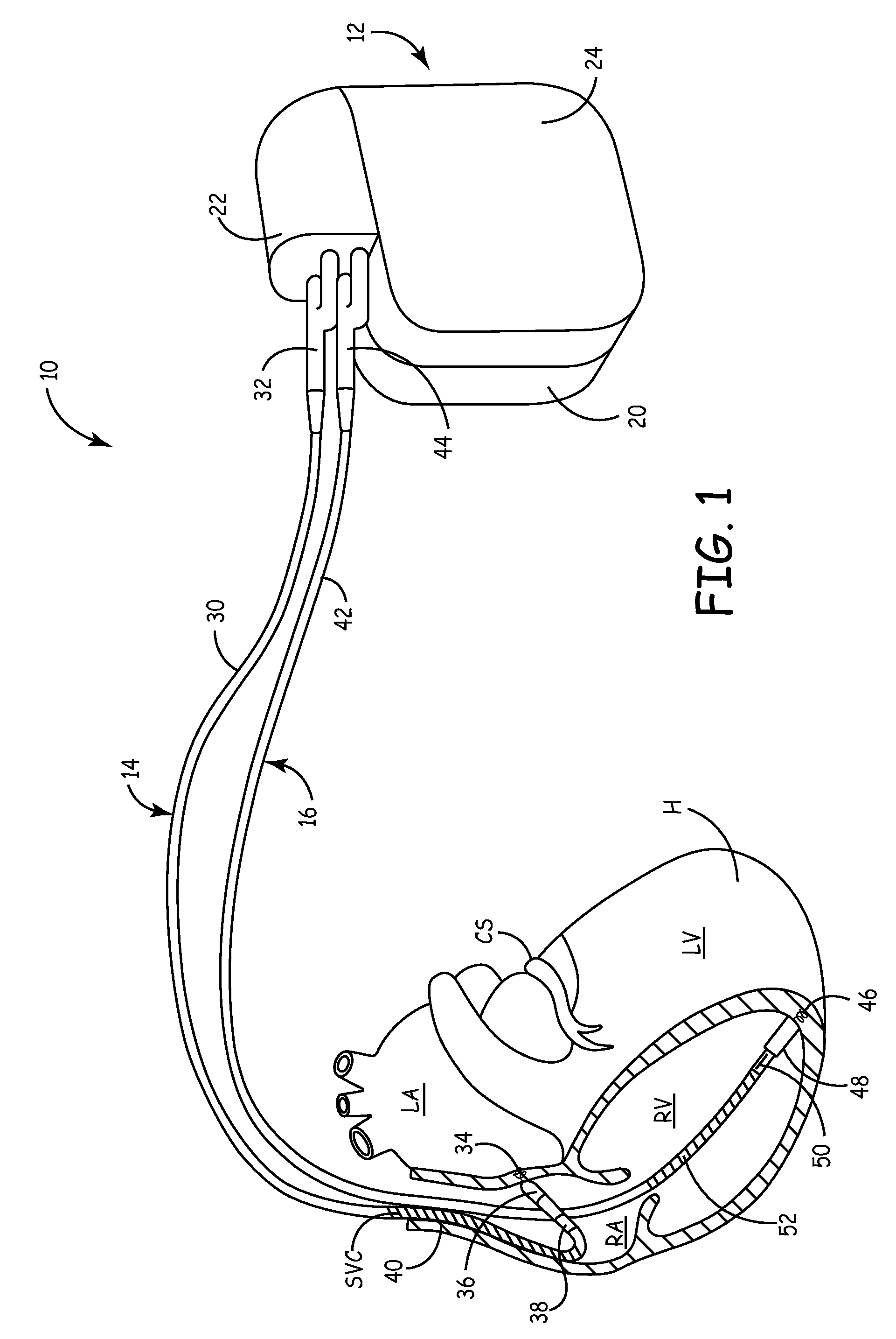
[0016]FIG. 1 shows implantable medical device 10, which provides dual chamber pacing and cardioversion / defibrillation therapy to heart H. In FIG. 1, heart H is shown in a partially cutaway view illustrating right atrium RA, left atrium LA, right ventricle RV, left ventricle LV, coronary sinus CS, and superior vena cava SVC.

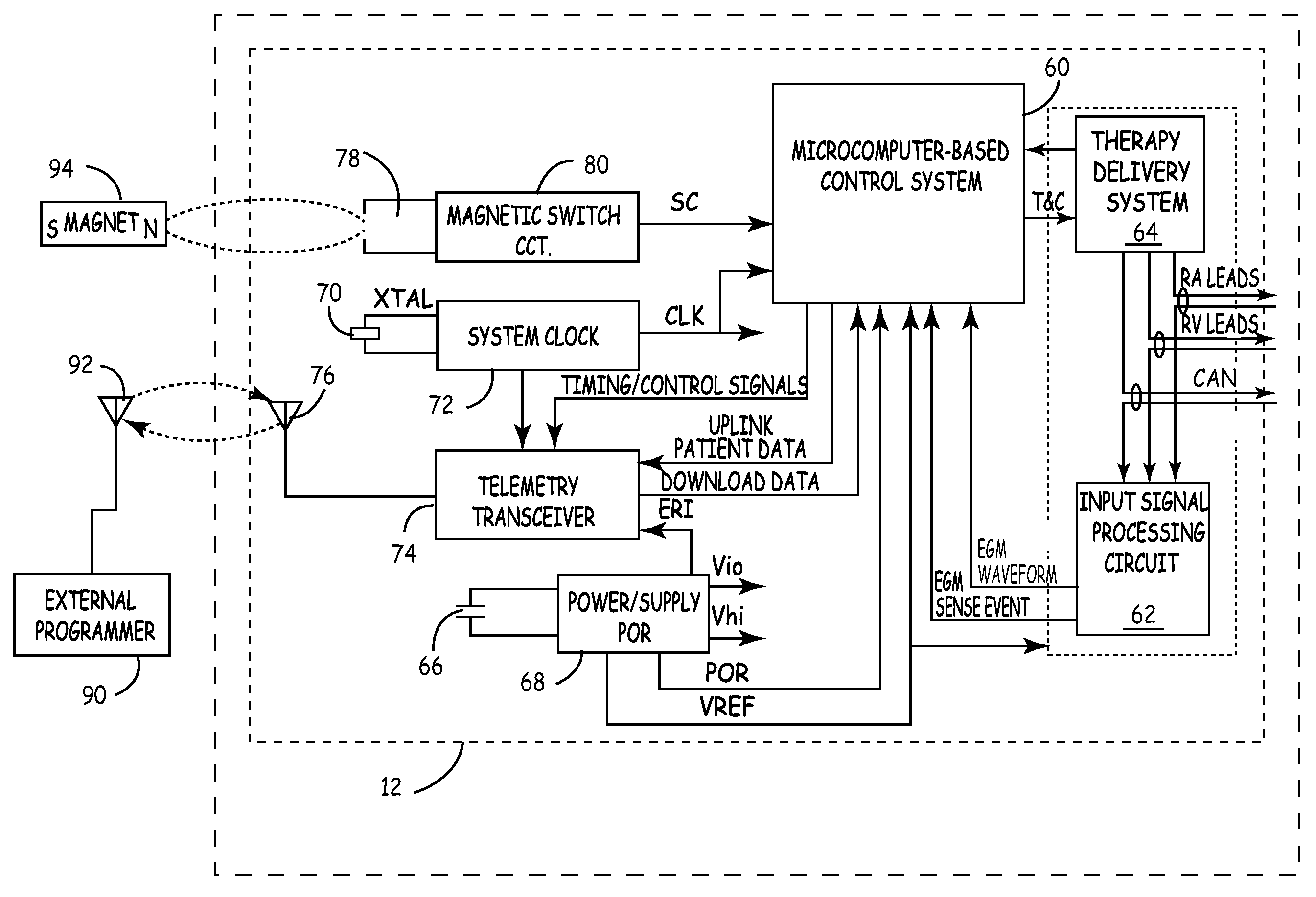
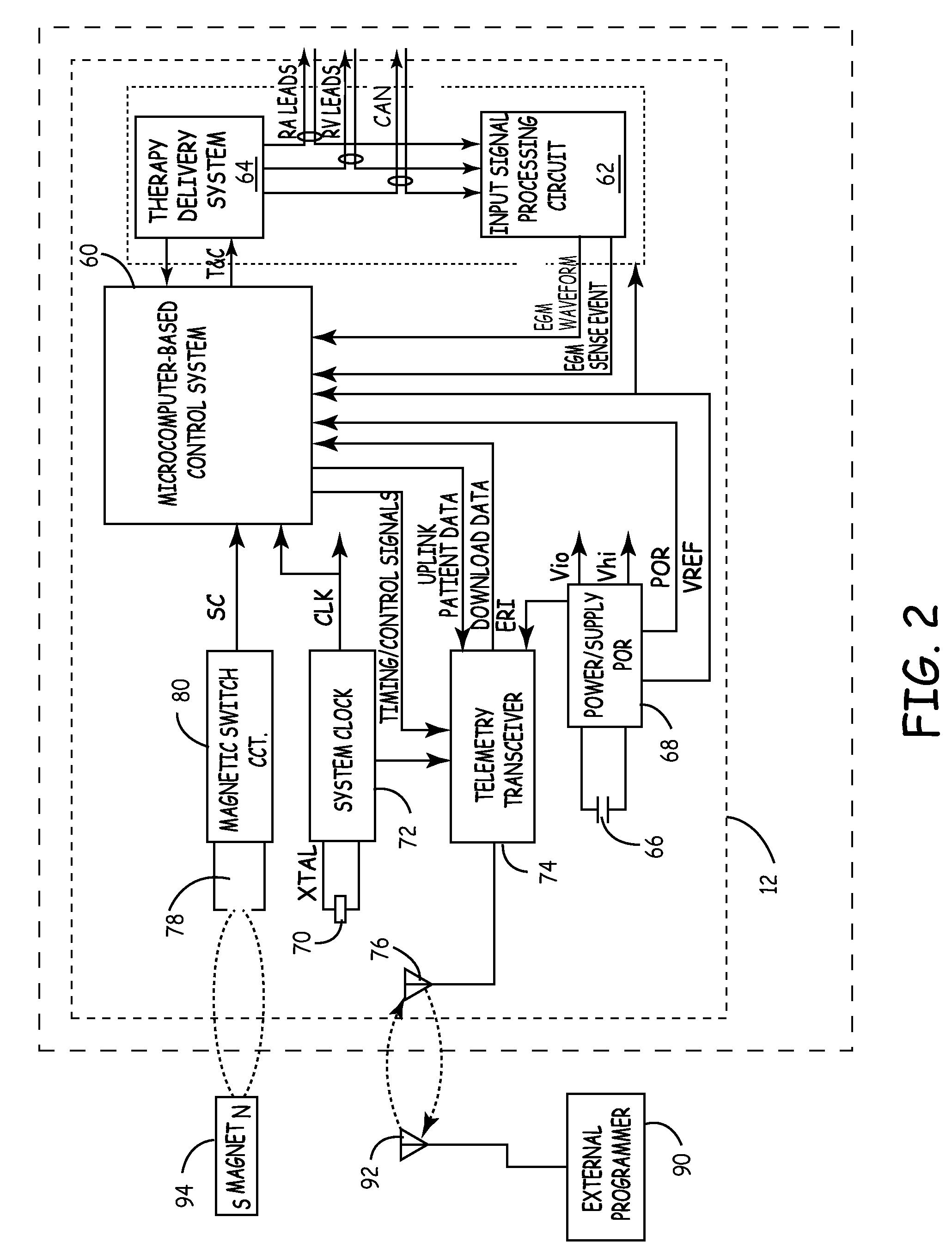
[0017]System 10 includes implantable cardioverter / defibrillator (ICD) 12, right atrial (RA) lead 14, and right ventricular (RV) lead 16. As shown in FIG. 1, ICD 12 includes housing or canister 20, header 22, and can electrode 24. The circuitry and power source of ICD 12 are located within housing 20. The circuitry communicates with leads 14 and 16 through electrical connectors within header 22. Can electrode 24 is formed on or is a part of the outer surface of housing 20, and acts as an electrode with respect to one or more of the electrodes carried by leads 14 and 16.

[0018]RA lead 14 is passed through the superior vena cava SVC into right atrium RA of heart H. RA...


PUM


Abstract

An implantable cardioverter defibrillator (ICD) automatically determines whether to use electrogram (EGM) signals sensed by a true bipolar electrode pair or those sensed by an integrated bipolar electrode pair. EGM signals from both the true bipolar pair and the integrated bipolar pair are simultaneously sensed and compared to determine which pair produced more accurate sensing of cardiac events. The more accurate source of EGM signals is selected and used in determining the therapy to be delivered.

Description

BACKGROUND OF THE INVENTION[0001]The present invention relates to implantable cardioverter defibrillators (ICDs), and more particularly to an ICD that automatically determines the most effective sensing electrode configuration.[0002]An implantable cardioverter defibrillator provides therapies for maintaining and restoring normal cardiac rhythms by pacing or by delivering electrical shock therapy for cardioverting or defibrillating the heart. The ICD is implanted pectorally, and one or more electrical leads connected to the ICD are inserted into or in proximity to the heart of the patient. The leads carry current from the ICD to the heart tissue to stimulate the heart using either low energy pacing pulses or high energy cardioversion / defibrillation shocks. The leads are also used for sensing electrogram (EGM) signals from the heart that are used by the ICD to determine therapy to be delivered.[0003]Within the ICD, sense amplifiers coupled to the leads amplify electrogram signals from...

Claims


Application Information

Patent Timeline
Patent Type & Authority Patents(United States)
IPC IPC(8): A61N1/08
CPCA61N1/3925A61N1/3962A61N1/3622A61N1/3704A61N1/39622
Inventor CASAVANT, DAVID A.COLLINS, ROBERT F.BROWN, MARK LGUNDERSON, BRUCE D.
Owner MEDTRONIC INC
Why Eureka
Try Eureka