
Document image scanning device

a scanning device and document image technology, applied in the direction of fixing agents, instruments, electrographic processes, etc., can solve problems such as distortion of scanned images, and achieve the effect of avoiding fluctuation of transportation loads

Inactive Publication Date: 2007-07-10
MURATA MASCH LTD
View PDF8 Cites 8 Cited by
  • Summary
  • Abstract
  • Description
  • Claims
  • Application Information

AI Technical Summary

Benefits of technology

[0008]The present invention has been made in consideration of the above-described circumstances. An advantage of the present invention is to provide a document image scanning device for scanning an image on both sides of an original document by transporting the original document once, which can eliminate a fluctuation of a transportation load at a scanning unit resulting from an influence of a transportation system and which can form a high-quality image without a distortion.
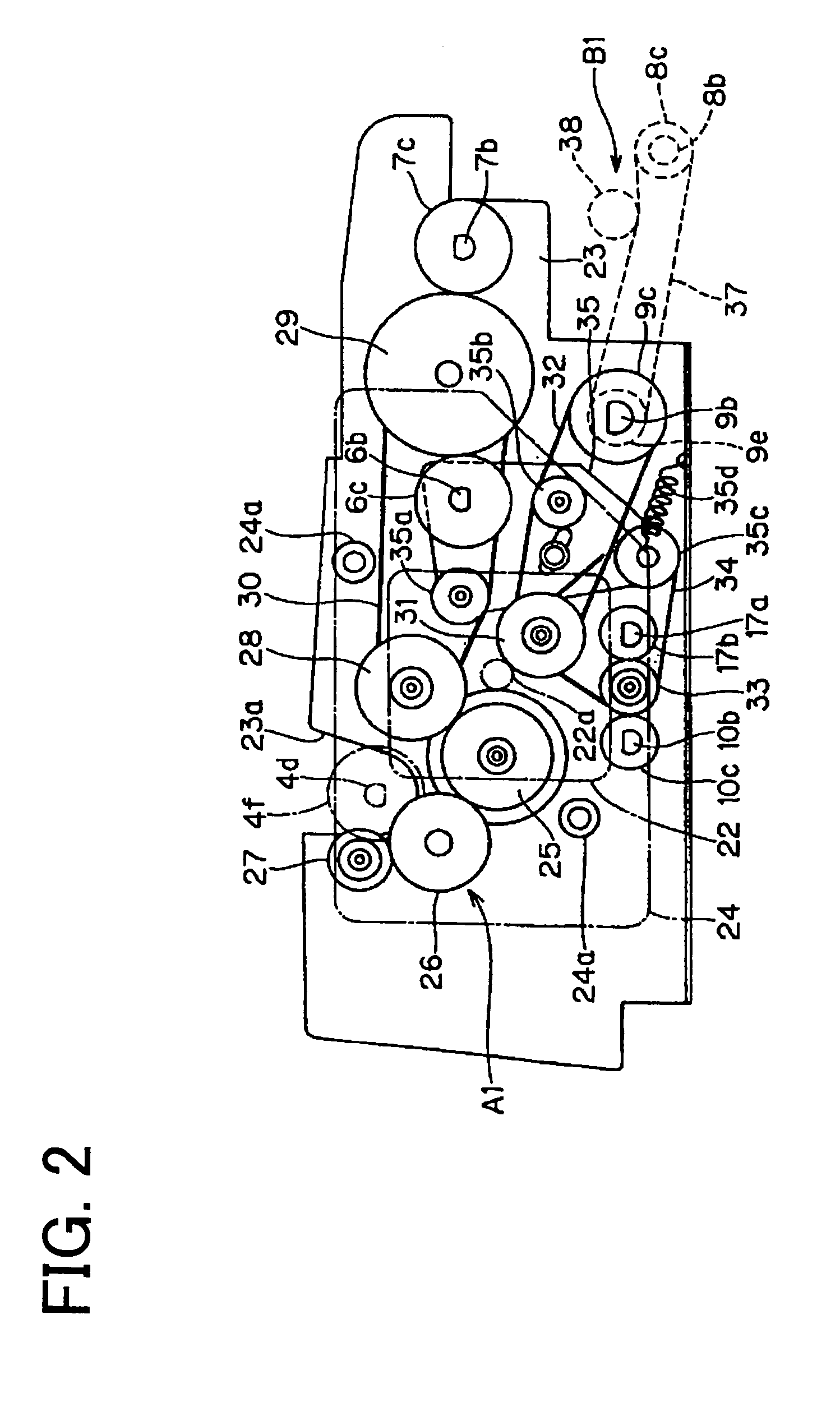
[0009]According to a first aspect of the present invention, a document image scanning device includes a document pickup unit, a separating and feeding unit, a plurality of transportation units, a first scanning unit and a second scanning unit. The document pickup unit picks up an original document from a document placing part. The separating and feeding unit separates and feeds picked up original documents one sheet at a time. The transportation units are provided to transport each separated and fed original document along a transportation path leading to a discharge tray. The first scanning unit scans an image on a first side of the original document transported through the transportation path. The second scanning unit scans an image on a second side of the original document after the first scanning unit. The plurality of the transportation units are classified into a first transportation system and a second transportation system. The first transportation system includes the picking up and the feeding of the original document at upstream of the first scanning unit. The second transportation system is located at front and back of the first and the second scanning units. The first and the second transportation systems are driven by a first and a second drive transmitting units, respectively. The first and the second drive transmitting units are distributed from an output shaft of one motor to transmit a driving force.
[0010]According to a second aspect of the present invention, the driving force from the output shaft is preferable to be diverged and transmitted by an engagement of gears. According to a third aspect of the present invention, the first scanning unit is preferable to be a movable scanner device and capable of being under a standstill standby state at a prescribed position on the transportation path at a side for scanning the first side of the transported original document. Meanwhile, the second scanning unit is preferable to be a contact image sensor and located at a prescribed position on the transportation path at a side for scanning the second side of the transported original document.
[0011]According to the aspects of the present invention, in the document image scanning device, the first transportation system including the picking up and the feeding of the original document and the second transportation system at the front and the back of the first and the second scanning units are classified into separate systems from one another. The first and the second transportation systems are respectively driven by the first and the second drive transmitting units, which are distributed from the output shaft of one motor to transmit the driving force. Therefore, the second transportation system is not influenced by the fluctuation of the transportation load of the first transportation system. As a result, an image scanned by the first and the second scanning units is not distorted. In particular, since the distance from the separating and feeding unit to the second scanning unit is long, if all of the transportation systems including the document transportation system at the front and the back of the second scanning unit are driven collectively by the drive transmitting systems, the fluctuation of the transportation load when the trailing edge of the original document departs from the separating and feeding unit and a next original document is fed in greatly influences the second scanning unit. However, in the present invention, the transportation system at the front and the back of the scanning units and the other transportation system located at the upstream are divided substantially from one another. Therefore, the above-mentioned influence by the fluctuation of the transportation load can be avoided.BRIEF DESCRIPTION OF THE SEVERAL VIEWS OF THE DRAWING
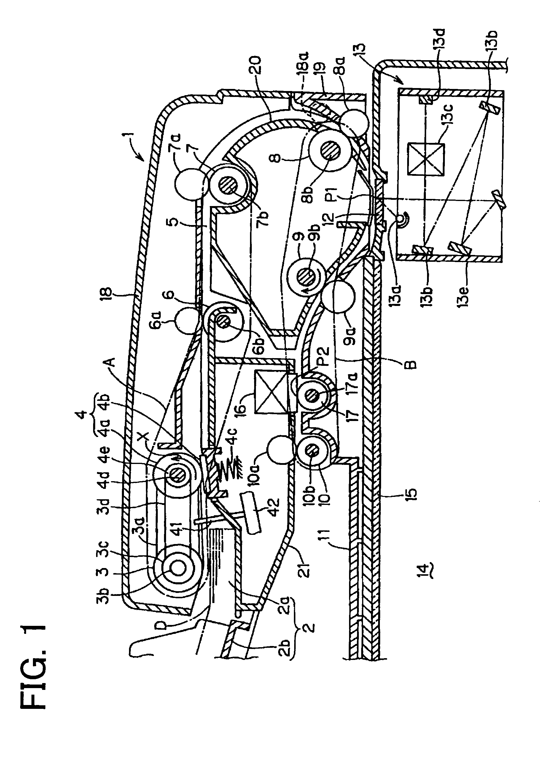
[0012]FIG. 1 is a lateral cross-sectional view showing an example of a document image scanning device according to an embodiment of the present invention.
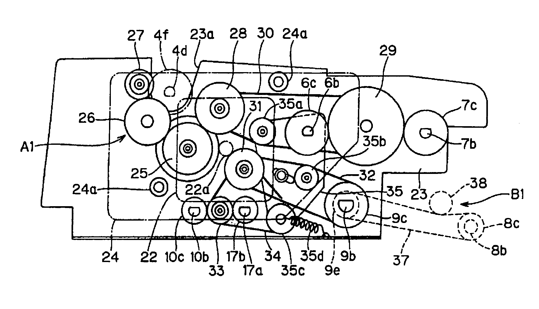
[0013]FIG. 2 is a front view showing drive transmitting mechanisms of each roller.

Problems solved by technology

The fluctuation of the transportation load and the vibration influence an image scanning process and cause a distortion of a scanned image.
However, in the second conventional document image scanning device, the scanning units are not provided at two positions along the transportation path so as to scan an image on both sides of the original document by transporting the original document once through the transportation path.
In addition, the second conventional document image scanning device does not consider the influence of the fluctuation of the transportation load in the transportation system of the original document at the image scanning unit for scanning an image on a second side of the original document.

Method used


Image

  • Document image scanning device
  • Document image scanning device
  • Document image scanning device

Examples


Embodiment Construction

[0016]Embodiments of the present invention will be described with reference to the drawings. FIG. 1 is a lateral cross-sectional view of the principal parts of a document image scanning device 1 having an ADF in a facsimile machine, a copying machine or a MFP having both a facsimile function and a copying function (also including a printer function). The document image scanning device 1 shown in FIG. 1 is formed as a duplex document image scanning device. While transporting original documents D one sheet at a time, the document image scanning device 1 scans an image on both sides of an original document D and outputs a digital signal. Further, in FIG. 1, an inner side of the page is a front side of the document image scanning device 1 and a front side of the page is a rear side of the document image scanning device 1.

[0017]At a document feeding opening 2a of the document image scanning device 1, a document tray 2b is set removably and provided slanting downward toward the document f...


PUM


Abstract

A document image scanning device includes two scanning units provided along a document transportation path for scanning both sides of an original document. A plurality of transportation systems are classified into a first transportation system upstream of a first scanning unit and a second transportation system located front and back of first and second scanning units. The first and the second transportation systems are driven by first and second drive transmitting units, respectively. The first and the second drive transmitting units are distributed from an output shaft of one motor to transmit a driving force.

Description

BACKGROUND OF THE INVENTION[0001]1. Field of the Invention[0002]The present invention relates to a document image scanning device which scans an image on both sides of an original document while transporting the original document by an Automatic Document Feeder (ADF) which operates by one motor in an image forming device such as a facsimile machine and a copying machine (including a Multi-Function Peripheral (MFP) of these machines).[0003]2. Description of Related Art[0004]In general, an electrophotographic copying machine and a facsimile machine include an ADF which separates original documents set on a document tray one sheet at a time and feeds each original document toward a scanning unit. In such an ADF, a separating roller and a plurality of transportation rollers are disposed along a document transportation path. The separating roller separates and feeds the original documents fed from the document tray one sheet at a time. The transportation rollers are provided downstream o...

Claims


Application Information

Patent Timeline
Patent Type & Authority Patents(United States)
IPC IPC(8): G03G11/00G06T1/00B65H5/00G03G15/00H04N1/00H04N1/04
CPCG03G15/602B65H3/0684B65H3/34B65H2801/06B65H2801/39
Inventor OYA, KAZUYUKINOSE, YOSHITAKA
Owner MURATA MASCH LTD
Learn More