Shoe rack

a shoe rack and shoe technology, applied in the field of shoe racks, can solve the problems of inability to place additional pairs of shoes on the shoe rack, difficulty in user access to shoes, waste of money,

Inactive Publication Date: 2007-07-31
CHI STEEL CO LTD
View PDF10 Cites 52 Cited by
  • Summary
  • Abstract
  • Description
  • Claims
  • Application Information

AI Technical Summary

Benefits of technology

[0007]Another objective of the present invention is that the support of the shoe rack is extendable so that whenever there is a demand exceeding supply of space, the user is able to extend the support so as to accommodate additional shoes.

Problems solved by technology

Because the conventional shoe resting brackets are fixed on the shoe rack it is sometimes difficult for the user to have access to the shoes especially when the shoe resting brackets are not orthogonal to the supports of the shoe rack.
Furthermore, the quantity of pairs of shoes placed on top of the shoe resting brackets is fixed such that there is no way to place additional pairs of shoes on the shoe rack.
Each shortcoming bothers the shoe rack user for there is no solution to the problem except buying another shoe rack of a different structure, which is impractical and a waste of money.

Method used


Image

  • Shoe rack
  • Shoe rack
  • Shoe rack

Examples


Embodiment Construction

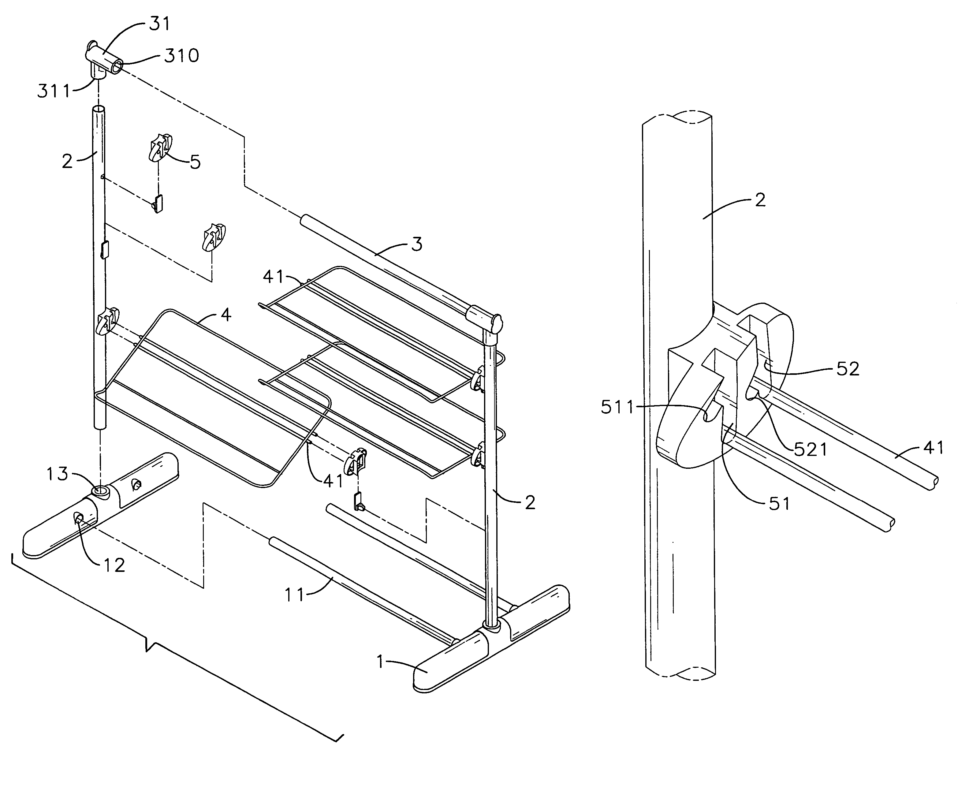
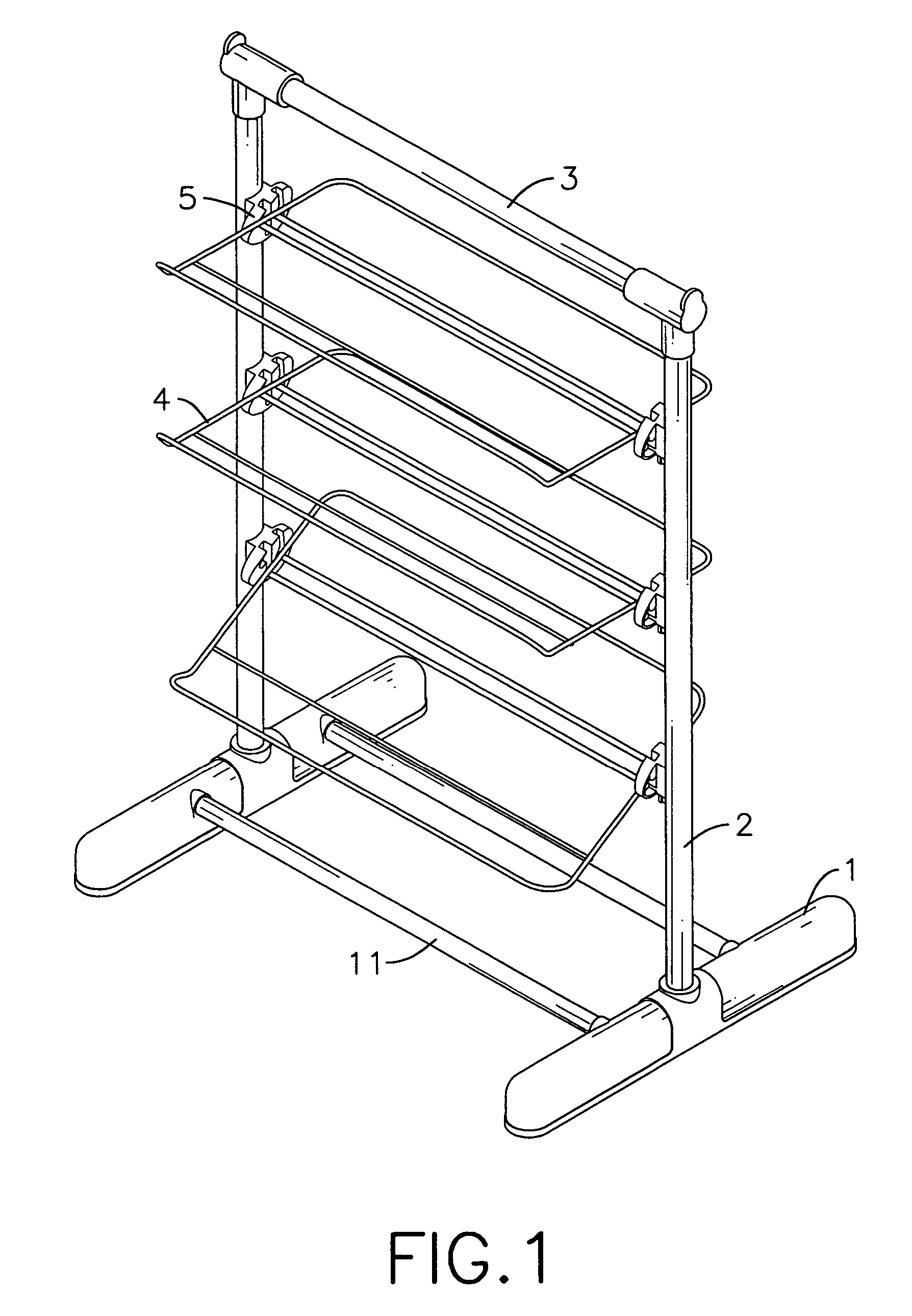
[0020]With reference to FIG. 1, the shoe rack in accordance with the present invention includes two elongated bases (1) interconnecting with each other via two connecting tubes (11), two supports (2) respectively and detachably mounted on top of the two elongated bases (1), a top tube (3) having a first end detachably connected to a free end of one of the supports (2) and a second end detachably connected to a free end of the other one of the supports (2) and multiple shoe resting brackets (4) detachably and adjustably mounted between the two supports (2) via fixtures (5).

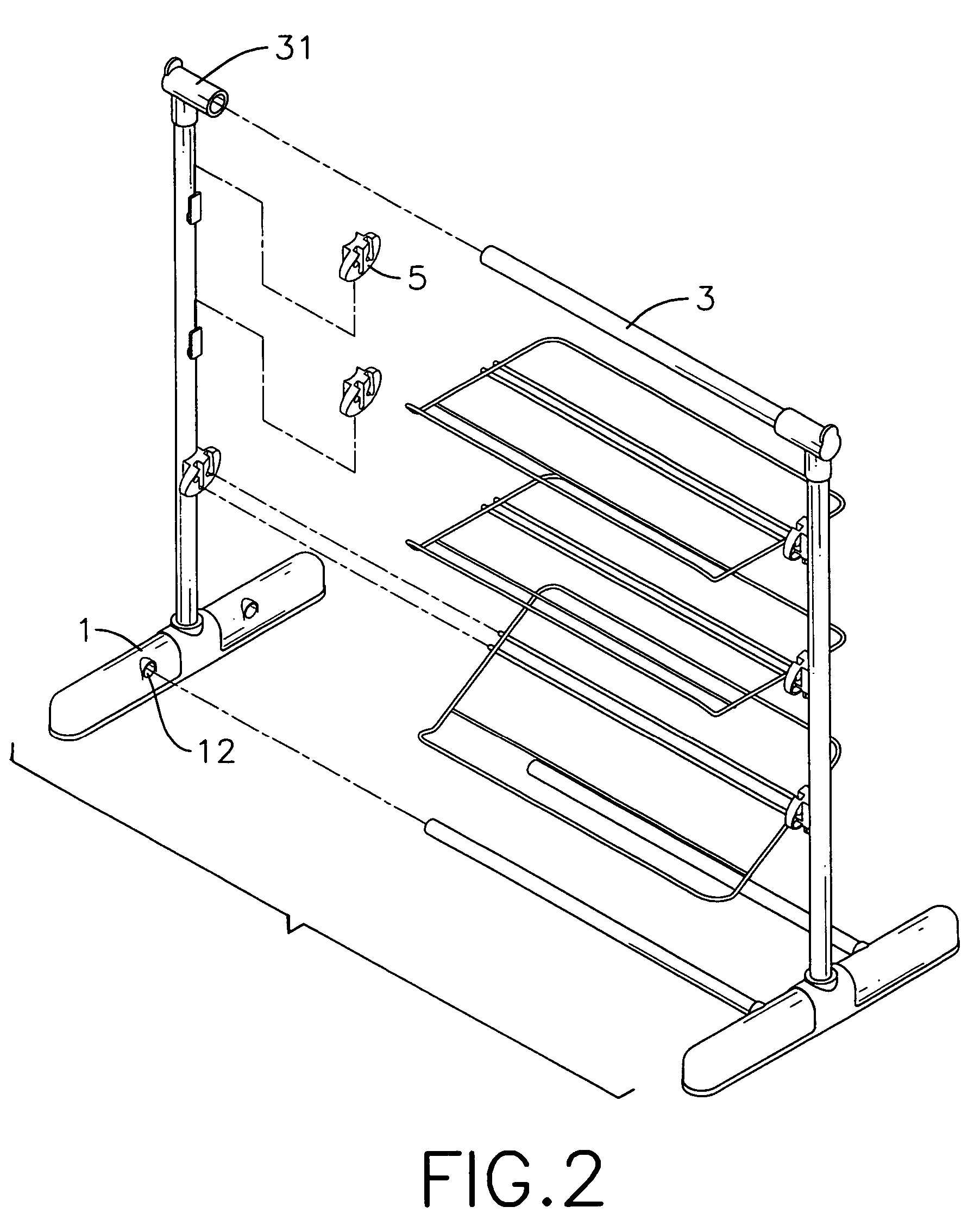
[0021]With reference to FIGS. 2 and 3, it is noted that each elongated base (1) has two first connecting holes (12) defined in an inner side face of the elongated base (1) to correspond to the two connecting tubes (11) such that the two connecting tubes (11) are able to extend into the corresponding first connecting holes (12) to combine the two elongated bases (1), and a second connecting hole (13) respectively de...


PUM


Abstract

A shoe rack has two supports respectively and detachably mounted on top of the two elongated bases, a top tube detachably connected to free ends of the two supports via connectors and multiple shoe resting brackets sandwiched between the two supports. Each shoe resting bracket is adjustably connected to the two supports via a fixture which a first cutout, a second cutout, a first indentation defined in a side face defining the first cutout and a second indentation defined in a side face defining the second cutout. When the rods are received in the first cutout and the second cutout, the shoe resting bracket is tilted relative to a horizontal surface and when the two rods are received in the first indentation and the second indentation, the shoe resting bracket is parallel to the horizontal surface.

Description

BACKGROUND OF THE INVENTION[0001]1. Field of the Invention[0002]The present invention relates to a shoe rack, and more particularly to shoe rack having shoe resting brackets stacked on top of each other and being adjustable to allow shoes to be displaced in different angles.[0003]2. Description of Related Art[0004]A shoe rack is provided for the users to place their shoes when not in use. Normally, a shoe rack has multiple shoe resting brackets stacked on top of each other so that the user is able to insert the shoes into the gaps between the shoe resting brackets and places the shoes on top of the shoe resting brackets. Because the conventional shoe resting brackets are fixed on the shoe rack it is sometimes difficult for the user to have access to the shoes especially when the shoe resting brackets are not orthogonal to the supports of the shoe rack. Furthermore, the quantity of pairs of shoes placed on top of the shoe resting brackets is fixed such that there is no way to place a...

Claims


Application Information

Patent Timeline
Patent Type & Authority Patents(United States)
IPC IPC(8): A47F7/08A47F5/08
CPCA47B57/04A47B61/04A47B96/024
Inventor WANG, CHI-CHUNG
Owner CHI STEEL CO LTD
Why Eureka
Try Eureka