Connector with thumb screw retention member

a technology of thumb screw and retention member, which is applied in the direction of connection, electrical apparatus, coupling device connection, etc., can solve the problems of limiting the connector space, affecting the cable routing, and more jackscrews affecting the closure of the cover

Inactive Publication Date: 2007-09-18
TE CONNECTIVITY CORP
View PDF9 Cites 21 Cited by
  • Summary
  • Abstract
  • Description
  • Claims
  • Application Information

AI Technical Summary

Benefits of technology

[0006]Optionally, the connector further includes a backshell at least partially enclosing the housing. The backshell includes a chamber between the contact loading end of the housing and a back wall of the backshell. The backshell includes side walls that have windows opening to the chamber to provide access to the edge portion of the locking member. The locking member includes a head portion enclosed by the back wall that does not extend axially outside the backshell. The housing includes a mating end opposite the contact loading end and a channel extending therebetween, and the locking member includes a shaft rotatably held in the channel even when the housing is in an unmated condition. The backshell includes a cable exit through an end wall of the backshell that is substantially perpendicular to a mating direction of the housing. The locking member includes a shaft rotatably held in the channel. The shaft includes a shoulder formed thereon. The channel has a step formed therein. The shoulder engages the step to provide a locking force when the connector is in a locked condition.

Problems solved by technology

However, in some systems, the chassis or board is mounted in a case with a hinged or otherwise closeable cover which limits connector space.
A disadvantage associated with jackscrews is that one or more of the jackscrews may interfere with the closing of the cover.
When several connectors are mounted on a panel, cable routing may become more of a problem.
In another disadvantage, the use of the typical two-jackscrew retention system generally precludes the provision of a right angle wire exit on the connector.

Method used


Image

  • Connector with thumb screw retention member
  • Connector with thumb screw retention member
  • Connector with thumb screw retention member

Examples


Embodiment Construction

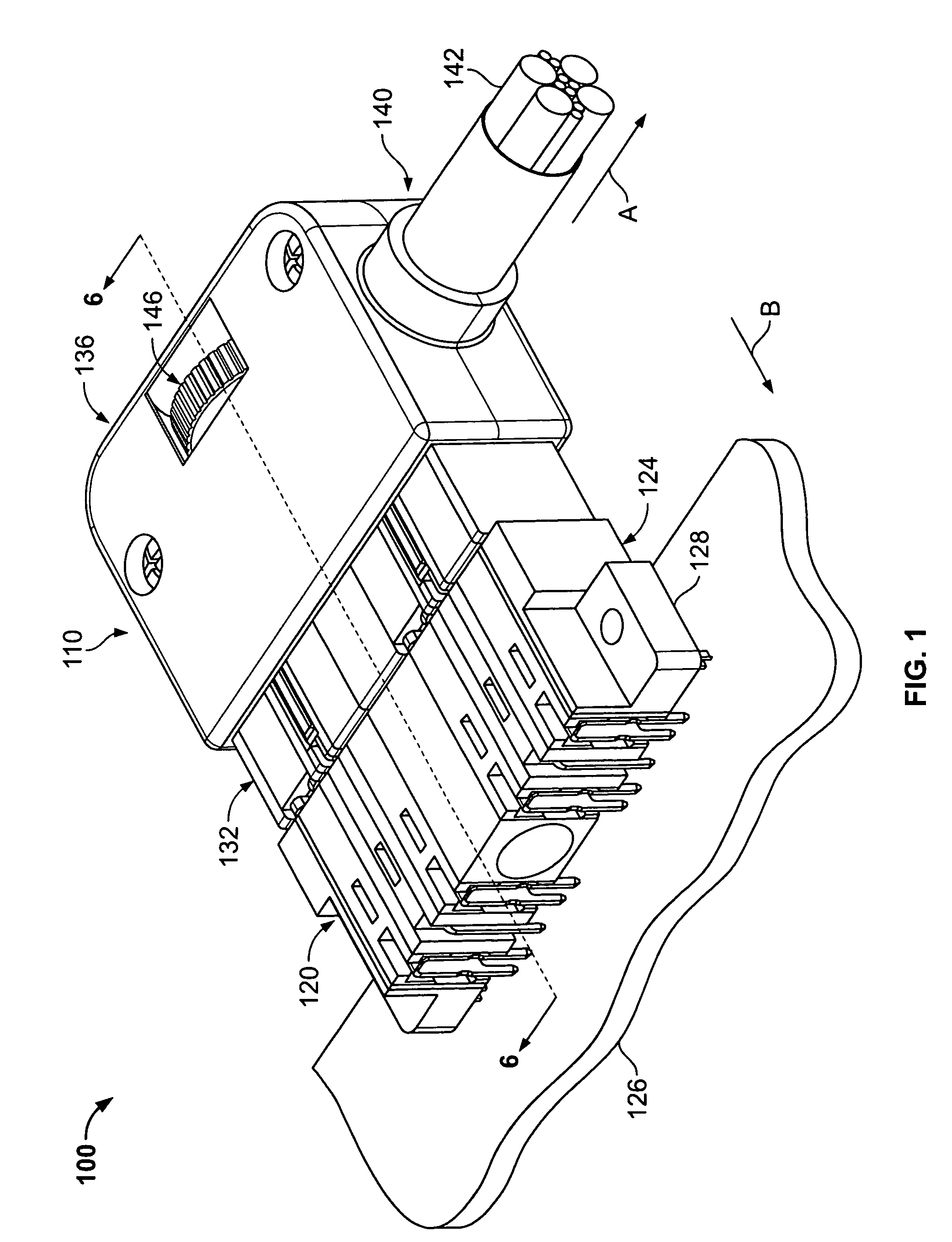
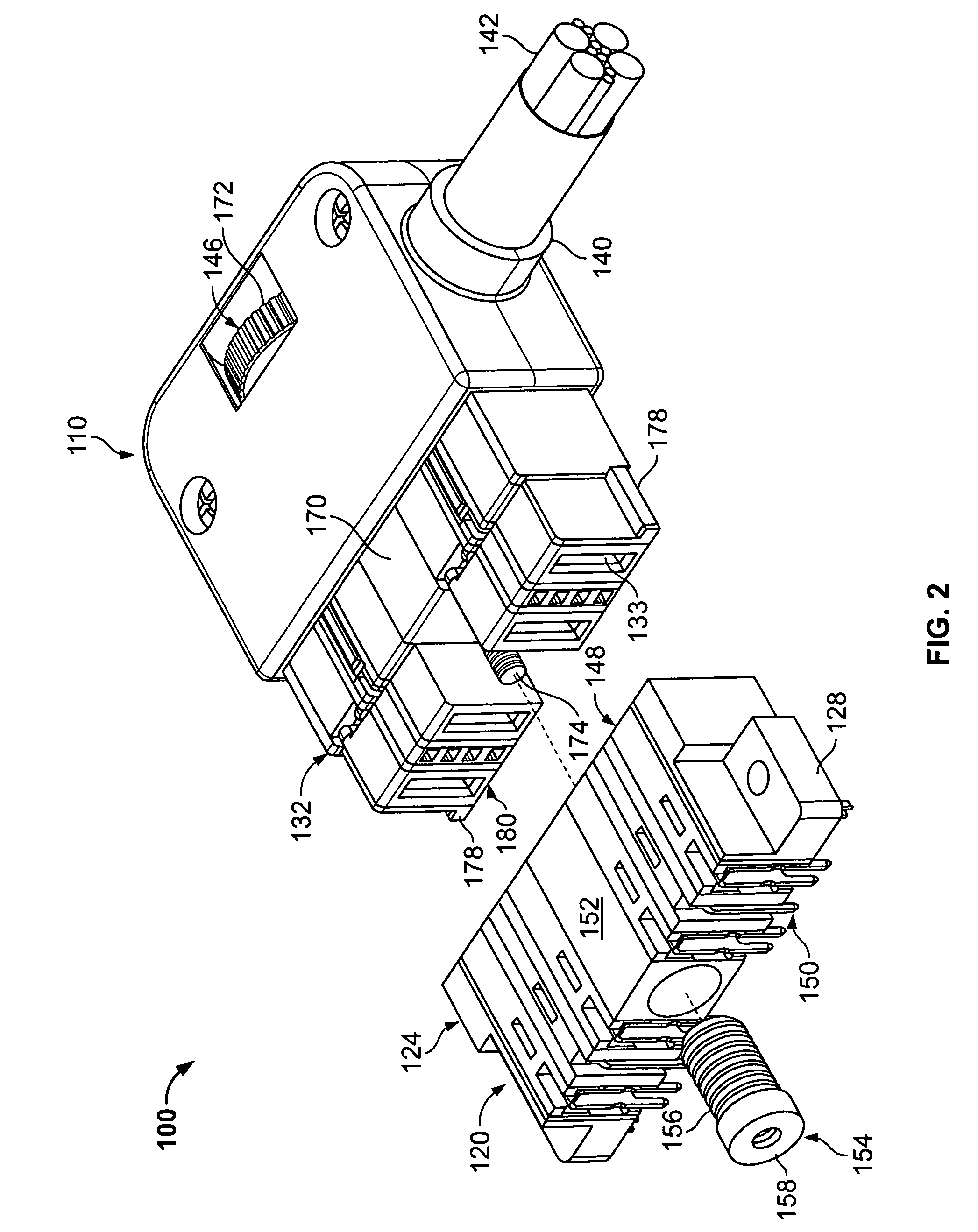
[0015]FIG. 1 illustrates a perspective view of a connector assembly 100 formed in accordance with an exemplary embodiment of the present invention. The connector assembly 100 includes a cable mounted connector 110 and a mating connector 120. As shown in FIG. 1, the cable mounted connector 110 is in a mated condition with the mating connector 120. The mating connector 120 includes a housing 124 and, in an exemplary embodiment, the mating connector 120 is mounted on a circuit board 126. The mating connector housing 124 is provided with mounting flanges 128 that may be used with fasteners (not shown) to secure the mating connector 120 to the circuit board 126.

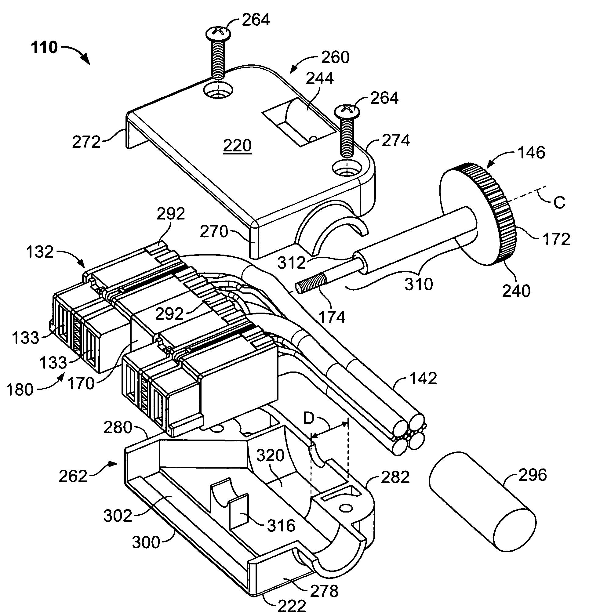
[0016]The cable mounted connector 110 includes a housing 132 that is held in a backshell 136. The backshell 136 is formed with a right angle wire or cable exit 140 such that a cable or wire bundle 142 exits the backshell 136 in the direction of the arrow A which is substantially perpendicular to the mating direction of the mating ...


PUM


Abstract

An electrical connector includes a housing having a contact loading end and a locking member rotatably mounted in the housing and substantially enclosed within the connector. The locking member has a circumferential edge portion that is exposed through a window of the connector to permit finger rotation of the locking member. A backshell at least partially encloses the housing. The backshell includes a chamber between the contact loading end of the housing and a back wall of the backshell. The backshell includes side walls that have windows opening to the chamber to provide access to the edge portion of the locking member.

Description

BACKGROUND OF THE INVENTION[0001]This invention relates generally to electrical connectors, and more specifically to a cable to board power connector assembly having a rotatable locking member.[0002]Some electrical systems include one or more connectors that are removably mounted in a chassis. For instance, in some applications, power supplies may be slid into a chassis. The power supplies can be removed for service or replacement. Typically, a cable mounted connector mates with a header connector on a board in the power supply. Jackscrews are typically used to assure that the connectors are reliably mated. However, in some systems, the chassis or board is mounted in a case with a hinged or otherwise closeable cover which limits connector space. Cables must be negotiated out of the case and the connectors must remain reliably mated when the case is closed. Jackscrews are commonly used in pairs with one jackscrew at each end of the connector. A disadvantage associated with jackscrews...

Claims


Application Information

Patent Timeline
Patent Type & Authority Patents(United States)
IPC IPC(8): H01R13/627
CPCH01R13/6215
Inventor TROUT, DAVID ALLISONWHYNE, RICHARD NICHOLAS
Owner TE CONNECTIVITY CORP
Why Eureka
Try Eureka